Before service: Isolate power and water and verify zero pressure. Read the safety instructions →
Station & exterior views
Identify the enclosure, connections and operator controls.
Before inspection or service
Automated pump station
The enclosure combines the high-pressure pump, motor, valves, gauges and electrical panel. The reference covers APS2501–APS2504 stations, a stated 0.25–2.5 gpm range and 1,000 psi operation; verify the actual station nameplate and quoted configuration.
| Item | Reference dimensions / features |
|---|---|
| Large enclosure | 36.75 × 19.5 × 16.5 inches |
| Stand | 36.25 × 24.25 × 30.25 inches |
| Controls | Omron PLC, hour meter, indicators and fan override |
| Field controls | 24 VAC humidistat and fan-relay circuits |
| Protection | HPS pressure proving, EDV depressurization and thermal relief |
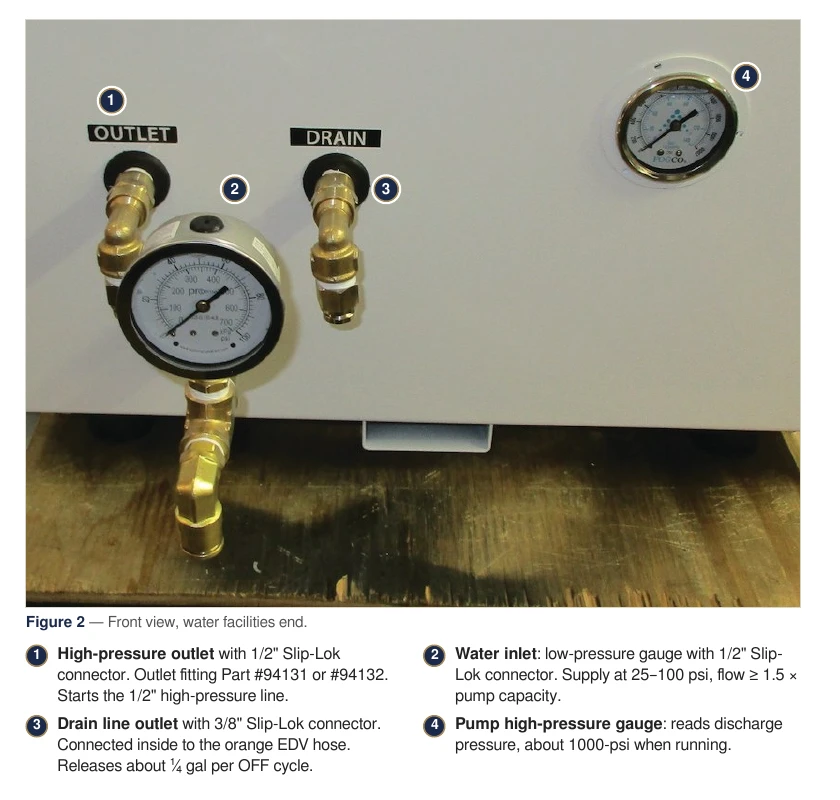
Water facilities end
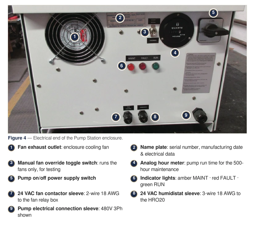
Electrical and operator end
| Callout | Component |
|---|---|
| 1 | Enclosure cooling exhaust |
| 2 | Nameplate: serial number, manufacture date and electrical ratings |
| 3 | Fan-only override toggle |
| 4 | Pump hour meter |
| 5 | Pump on/off switch |
| 6 | Amber MAINT, red FAULT and green RUN indicators |
| 7 | Fan-control sleeve: two-wire 18 AWG |
| 8 | Humidistat sleeve: three-wire 18 AWG |
| 9 | Pump power entry |
Interior components
Locate electrical and hydraulic equipment with numbered source illustrations.
Electrical panel
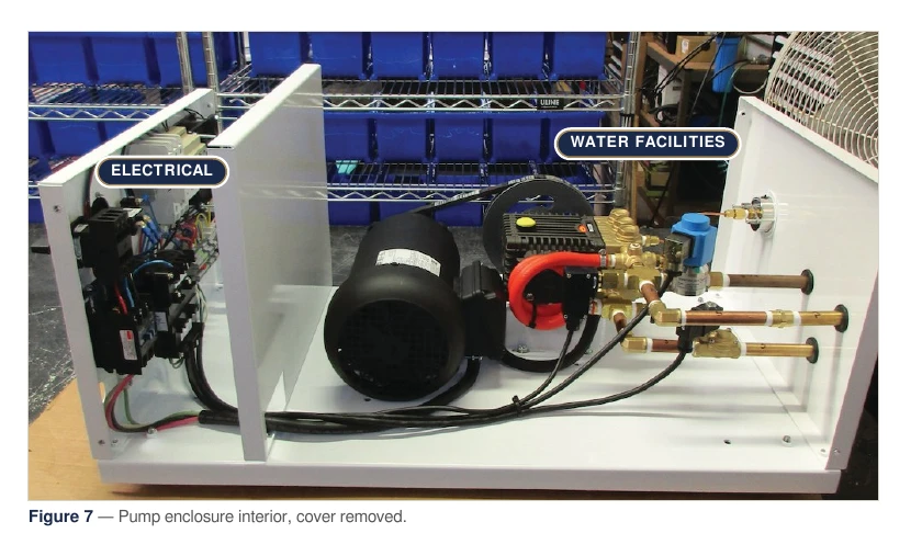
The large enclosure’s electrical panel uses three ¼-20 pan-head screws; the medium version uses two ¼-20 hex-head screws. Isolate the station before access.
| Component | Purpose / identification |
|---|---|
| Omron PLC | Sequencing and fault logic |
| Main breaker / circuit fuses | Internal circuit protection; ratings depend on station |
| 24 V transformer | Humidistat and fan-control supply |
| 480 V step-down transformer | 93301, 150 W, 480 × 230; where fitted |
| Cube relay | Humidistat start signal to Input 0 |
| Motor contactor | Pump-motor switching |
| Terminal blocks | NEUTRAL, HOT, RELAY and FAN CONTROL |
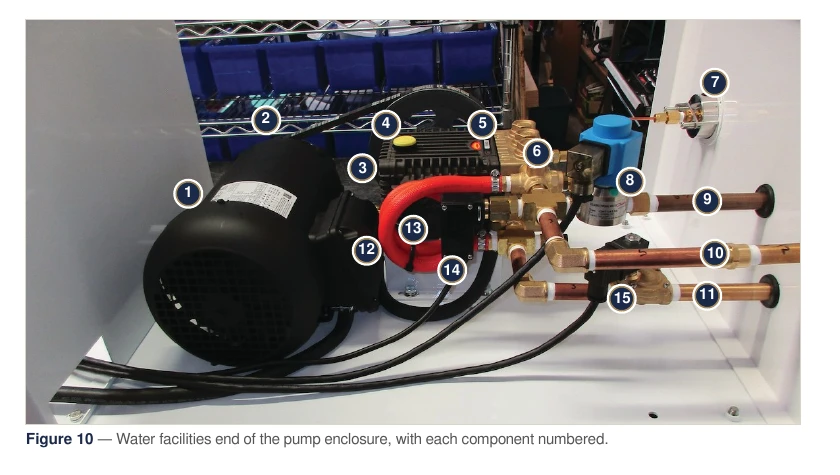
Water facilities: numbered component key
| No. | Component | Part / function |
|---|---|---|
| 1 | Electric motor | Belt drive |
| 2 | Belt and pulley | Inspect during 500-hour service |
| 3 | Bypass hose / thermal relief | Returns bypass water; thermal protection |
| 4 | Oil fill cap | 93222 oil; specified 15 oz fill |
| 5 | High-pressure pump | EP1812S17 / EP1508S34 |
| 6 | Unloader / pressure regulator | 93521 |
| 7 | Discharge gauge | System-pressure indication |
| 8 | EDV | 95001 |
| 9 | Drain hose | To exterior ⅜-inch drain outlet |
| 10 | High-pressure outlet | 94131 / 94132 |
| 11 | Low-pressure inlet | Supply connection |
| 12 | High-pressure hose | From regulated discharge |
| 13 | Oil sight window | Reference level: half full |
| 14 | HPS | 93656 |
| 15 | Inlet solenoid | 93368 / 93596 |
Parts by assembly
Find the component family, then check the current catalog for the exact part.
Pump, filtration and electrical parts
| Part | Description |
|---|---|
| EP1812S17 / EP1508S34 | High-pressure pumps |
| 93521 | Unloader valve |
| 95001 | EDV |
| 95003 / 95004 / 95005 | EDV coil voltage variants |
| 95002.DIN | EDV connector |
| 93368 / 93596 | Inlet valve, 115 V / 230 V |
| 93656 | Black HPS |
| 92609 / 92608 / 95062 | Filter housing / cartridge / wrench |
| 93222 | 16 oz pump-oil bottle |
| 93301 | 480-to-230 V step-down transformer |
| Zfeetevo | EP rail mounting foot set |
Controls and fans
Use the installed motor nameplate for voltage, current and wiring. The fan component reference contains more detailed model comparisons.
Tubing and Slip-Lok fittings
| Part | Description |
|---|---|
| 90063 / 93072 | ⅜-inch nylon tube, 500-foot / 100-foot rolls |
| 90550 / 90551 | ½-inch nylon tube, 500-foot / 100-foot rolls |
| 92714 / 92680 | ⅜-inch / ½-inch coated wall clamps |
| 92702 / 95702 | ⅜-inch / ½-inch coupling |
| 92703 / 95703 | ⅜-inch / ½-inch 90° elbow |
| 92704 / 95704 | ⅜-inch / ½-inch tee |
| 92854 | ½-inch Slip-Lok × ⅜-inch MNPT transition |
| 92709 | ⅜-inch Slip-Lok × ⅜-inch FNPT transition |
| 94131 / 94132 | Pump outlet fittings |
Rings, valves and nozzles
| Part | Description |
|---|---|
| 93706 / 93718 | 15-inch / 18-inch bare mist rings |
| 93712 / 93711 | 24-inch / 27-inch bare mist rings |
| MR24-12 / MR27-14 | Complete ring and ball-valve assembly sets |
| 92707 | ⅜-inch Slip-Lok × ⅜-inch MNPT; two per valve assembly |
| 92632 | ⅜-inch stainless-steel ball valve |
| 93163 | ⅜-inch Slip-Lok × ⅛-inch MNPT ring adapter |
| 1.85N / 2.64N / 3.97N | Orange / black / white nozzle sizes |
| 5.29N / 7.94N / 10.58N | Red / blue / clear nozzle sizes |
| 51000 | 5-micron nozzle filter |
| 92520 | 10/24-to-12/24 thread adapter |
| 94506 | 6-inch stainless-steel nozzle extension |
Parts & references
Continue with related guides, parts and the original PDF.
Original & related PDFs
This web guide is adapted from the IHC reference linked below. The original PDF retains its diagrams, document revision and printable layout.