Before service: Isolate power and water and verify zero pressure. Read the safety instructions →
Construction & operation
Understand the ruby orifice, filter and mechanical anti-drip valve.
Before inspection or service
Three-part nozzle assembly
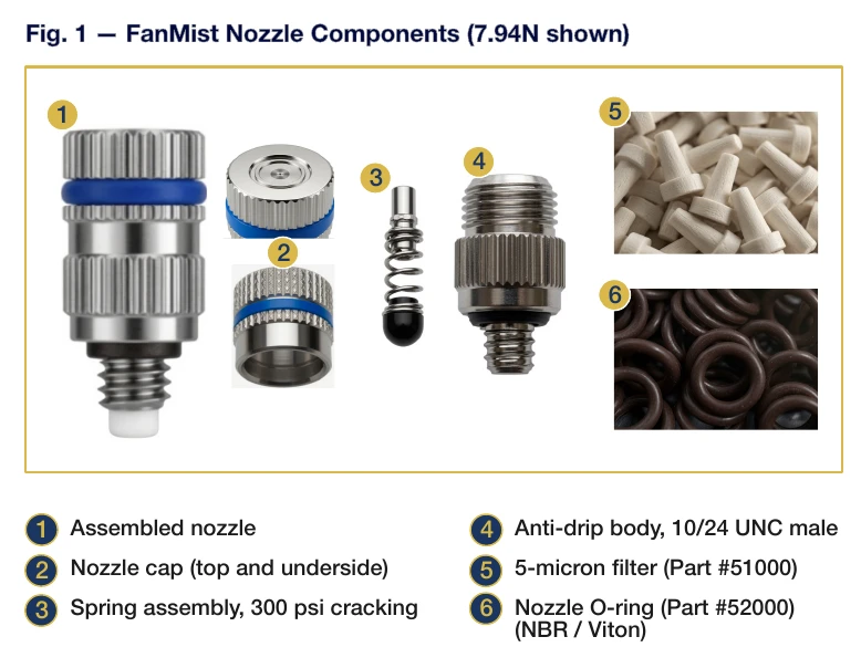
FanMist nozzles use a 303 stainless-steel body, ruby orifice insert and spring-operated anti-drip assembly. The cap’s color band identifies the orifice size. A 5-micron filter in the threaded inlet protects the orifice.
The cap, spring assembly and anti-drip body assemble finger-tight. The O-ring provides the seal; do not use pliers or a wrench. The normal thread is 10/24 UNC male, with 12/24 UNC available by special order.
Opening and closing pressure
As supply pressure rises, filtered water lifts the spring from its seat at approximately 300 psi and passes through the ruby orifice. Rated output is measured at 1,000 psi.
When the EDV opens at shutdown or on power loss, pressure drops below the cracking point and each nozzle’s spring closes it. This prevents weak discharge as pressure falls. Ruby orifices resist mineral buildup, but they still require suitable water treatment and filtration.
Nozzle & mist-ring output
Compare rated flows and calculate the output of a complete ring.
Six nozzle sizes at 1,000 psi
The reference reports tested output with the filter installed. Small differences between rounded flow and output values are expected. To estimate output from flow, multiply gpm by 8.34 lb/gallon and 60 minutes/hour.
Mist-ring output by size
All values are lb/hr at 1,000 psi. Ring output equals the port count multiplied by the individual nozzle rating.
| Ring / ports | 1.85N | 2.64N | 3.97N | 5.29N | 7.94N | 10.58N |
|---|---|---|---|---|---|---|
| 12-inch / 4 | 7.4 | 10.6 | 15.9 | 21.2 | 31.8 | 42.3 |
| 15-inch / 6 | 11.1 | 15.8 | 23.8 | 31.7 | 47.6 | 63.5 |
| 18-inch / 8 | 14.8 | 21.1 | 31.8 | 42.3 | 63.5 | 84.6 |
| 24-inch / 12 | 22.2 | 31.7 | 47.6 | 63.5 | 95.3 | 127.0 |
| 27-inch / 14 | 25.9 | 37.0 | 55.6 | 74.1 | 111.2 | 148.1 |
Check the loading ratio
The IHC guide targets more than 75 CFM for each lb/hr of water. At 10,000 CFM, that corresponds to roughly 133 lb/hr per fan; at 5,300 CFM, roughly 71 lb/hr. Use the actual fan’s rating.
With 7.94N nozzles, a 14-port ring delivers 111.16 lb/hr and a 10,000 CFM fan provides a ratio near 90. An 8-port ring delivers 63.52 lb/hr and a 5,300 CFM fan provides a ratio near 83. The largest 10.58N nozzles fall below the guide’s ratio in both examples.
Ordering & care
Confirm thread, quantity and supply conditions before ordering.
Packaging and thread options
- Order in multiples of 10; each pack contains ten individually sealed nozzles.
- Each nozzle includes its white 5-micron filter. Do not discard it as packaging.
- Stock thread: 10/24 UNC. The reference lists 12/24 special orders at 100 or more and a three-week lead time; confirm current availability with IHC.
- Adapter 92520 converts the 10/24 connection to 12/24.
- Install finger-tight and verify ring output, fan airflow and pump capacity before changing nozzle sizes.
Parts & references
Continue with related guides, parts and the original PDF.
Related parts
- 1.85N303 stainless steel nozzle — 1.85 lbs/hr, orange band
- 2.64N303 stainless steel nozzle — 2.64 lbs/hr, black band
- 3.97N303 stainless steel nozzle — 3.97 lbs/hr, white band
- 5.29N303 stainless steel nozzle — 5.29 lbs/hr, red band
- 7.94N303 stainless steel nozzle — 7.94 lbs/hr, blue band
- 10.58N303 stainless steel nozzle — 10.58 lbs/hr, clear band
Original & related PDFs
This web guide is adapted from the IHC reference linked below. The original PDF retains its diagrams, document revision and printable layout.