Before service: Isolate power and water and verify zero pressure. Read the safety instructions →
Intervals & warning signs
Plan service by pump run hours and recognize conditions that require a shutdown.
Before inspection or service
Stop when the pump shows distress
The PLC tracks pump run hours and lights the amber MAINT indicator every 500 hours. Keep the date, hour-meter reading, work performed, parts used and technician’s initials in a service log.
Maintenance by interval
Component-specific instructions may require a shorter interval. Confirm the installed pump’s schedule with IHC; the EP reference contains differing oil-interval statements.
| Interval | Work |
|---|---|
| Before startup | Water supply on; filter clean; treatment operating; inlet conditions correct; no visible scale or leaks. |
| First 50 hours | Break-in oil change. |
| Every 500 hours | Change oil and pre-filter; inspect belt and pump head; reset the maintenance timer after service. |
| Annually at minimum | Oil and pre-filter changes even if 500 hours have not elapsed, per this FanMist maintenance reference. |
| 2,000–2,500 hours or first leak | Replace pump water seals / V-packings; inspect sooner if symptoms appear. |
| 2,500 hours or as needed | Service six check valves and inspect plungers. |
| As needed | Nozzles, inlet valve, EDV and Slip-Lok seals. |
| Off-season | Run 10–15 minutes every 14 days, or drain completely. |
500-hour service
Complete oil, filtration, belt and pump-head checks before resetting the reminder.
Pump oil change
The oil bottle contains 16 oz; the stated pump fill is 15 oz. Do not pour in the entire bottle automatically.
- Run the assembled pump for approximately 15 minutes to warm the oil, then stop and lock out power. Isolate the system and verify zero pressure before opening equipment.
- Remove the yellow breather cap and crankcase drain cap. Collect and dispose of the used oil appropriately.
- Refit the drain cap. Add the specified 15 oz of 30-weight non-detergent pump oil, part 93222, through the breather opening.
- Check that the sight window is half full. Refit the breather cap hand-tight and reinstall covers.
- Restore the system for a brief guarded test. Check for leaks and record the service.
Pre-filter, belt and pump head
- Shut off the supply and relieve pressure before opening filter housing 92609. Use wrench 95062 and replace cartridge 92608, the 9¾-inch, 5-micron element. Check for leaks after restoring water.
- Inspect the drive belt for wear, cracks and slippage. Excessive tension can damage the crankshaft bearing.
- Look for water or oil at the pump head. Water leaking underneath the brass head requires prompt seal attention.
- After all service is complete, press PLC buttons 3 + 4 together to clear the amber reminder.
Valves, plungers & seals
Identify wear and use the pump-specific service and torque information.
Six pump check valves
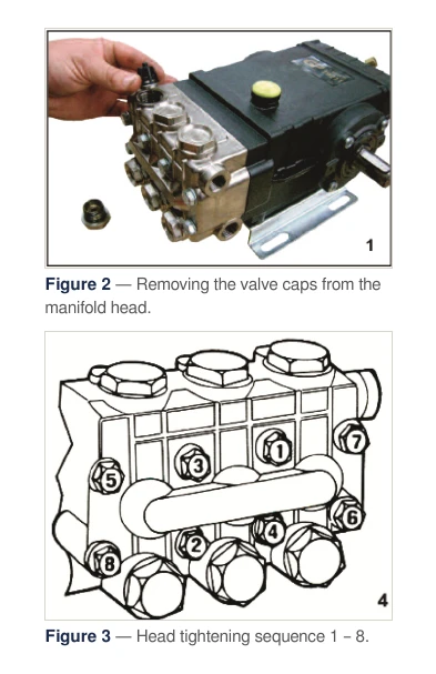
Debris or mineral buildup in a valve can cause vibration, pressure loss and knocking. At the scheduled service, isolate the equipment, remove the caps and inspect each valve’s spring, seat, plastic housing and O-rings. Clean the isolated head without losing the O-rings beneath the valves.
Install sound or new O-rings and the matched preassembled valves. Inlet and outlet cap torques differ; use the model-specific torque table. Do not use the head-bolt tightening sequence as a valve-cap torque specification.
Plunger inspection and replacement
- With the system isolated, remove the manifold head carefully so the ceramic plungers are not damaged.
- Remove the plunger screw and plunger. Preserve and reinstall the slinger washer if it comes away.
- Fit the new O-ring and backup ring to the screw, with a light film of compatible grease on the O-ring.
- Press the screw into the replacement plunger and reassemble in the original order using the model’s specified torque.
V-ring packings and seal failure
Water under the manifold, or milky and foamy oil with leakage, requires investigation before further operation. Worn seals can admit water into the crankcase and damage lubrication. The reference describes seal life ranging from 500 to 2,500 hours depending on water quality and operating conditions.
- Premature failure can result from damaged plungers, abrasive water, excess inlet pressure or temperature, or running without water.
- Use the matched pump’s limits; do not treat the maximum rating of a different component as an operating setting.
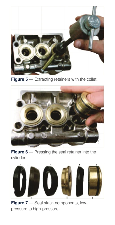
- Remove the isolated manifold head and use the correctly sized extractor collet to remove retainers, V-packings and head rings.
- Using the insertion tool, fit the front head ring, V-packing and long-life ring, pressing them fully home.
- Fit the intermediate retainer, then the rear head ring, V-packing and main seal retainer.
- Repeat for each cylinder. Inspect plungers for damage and change contaminated oil before returning to service.
Component care & flushing
Maintain nozzles and valves, and remove installation debris before startup.
Nozzle cleaning and Slip-Lok fittings
For a leaking Slip-Lok fitting, prepare a square, smooth tube end, push fully home and pull back to lock. If leakage persists, inspect the primary O-ring, backup ring and fitting after depressurizing.
- Isolate power and water and depressurize before removing a nozzle.
- Unscrew the cap and remove the spring assembly. Use the source’s 50/50 warm-water and vinegar cleaning option, then rinse thoroughly.
- Reassemble with the white 5-micron filter in place and install finger-tight only.
Valves and pressure protection
- Inlet solenoid: investigate no flow on a call, flow while off or no normal click; check the matched coil and connector.
- EDV: verify opening on pump stop and prompt pressure release below the nozzle closing threshold. Clear an isolated drain restriction.
- HPS: correct leaks or supply faults before cycling the start signal to reset. Never bypass it.
- Thermal relief: the reference describes opening above 145°F and releasing about 8 oz. Frequent discharge calls for a review of bypass heating and pump sizing.
Mandatory line flushing
Flush after installation and after major line work, with nozzles removed. Prepare the system, lifting access, collection buckets and secured drain wands before operating the pump. Do not begin continuous normal operation until flushing is complete.
Work outward from the nearest fan with coordinated pump-station and lift operators. Each ring is flushed through its two top ports, with the other ports plugged and the fan locally switched off. The reference specifies 1.5–3 gallons per ring and a roughly 10-second start delay.
Water quality & seasonal care
Protect water quality during operation and avoid stagnant off-season water.
Water-quality checks
Maintain particulate filtration and appropriate treatment for dissolved minerals. Softening controls hardness; RO removes dissolved minerals. Treatment selection also depends on whether airborne mineral residue is acceptable in the process.
| Parameter | FanMist maintenance reference |
|---|---|
| TDS | Below 150 ppm; ideally below 100 ppm |
| Hardness | Below 10 grains/gallon |
| pH | 6.5–8.5 |
| Temperature | Below 145°F |
| Chlorine | Below 1 ppm |
| Supply flow | At least 1.5 times rated station pump capacity, continuously |
Shutdown, restart and service records
- Off-season: choose either a 10–15 minute exercise cycle every 14 days or complete draining.
- At season start: fit a new pre-filter, change oil if due, verify treatment is in run mode and complete one full startup/shutdown cycle.
- Record date, hour meter, work, replacement part numbers and initials. Keep the log with the pump station.
- The source gives five years for pump defects and two years for other equipment; normal wear and maintenance-related damage are excluded. Consult the original warranty terms.
Parts & references
Continue with related guides, parts and the original PDF.
Related parts
Original & related PDFs
This web guide is adapted from the IHC reference linked below. The original PDF retains its diagrams, document revision and printable layout.