Before service: Isolate power and water and verify zero pressure. Read the safety instructions →
Models & specifications
Match the pump model before ordering a replacement or service kit.
Before inspection or service
EP Series in the FanMist station
The General Pump EP Series is a belt-driven triplex plunger pump with a forged-brass manifold, solid ceramic plungers and a right-hand solid shaft. In FanMist service, the station regulates discharge to approximately 1,000 psi.
The manufacturer’s maximum pump pressure and flow ratings are not the installed FanMist operating settings. Station motor, pulley ratio and regulation determine the actual output.
EP1812S17 and EP1508S34
Both models have a 15 oz crankcase, ½-14 BSP-F inlet, ⅜-19 BSP-F discharge and approximately 15.4 lb weight. The EP source lists a 165°F maximum fluid temperature and a flooded inlet up to 70 psi. Confirm the installed pump’s inlet limit when setting the station supply.
| Specification | EP1812S17 | EP1508S34 |
|---|---|---|
| Rated speed | 1,750 RPM | 3,400 RPM |
| Maximum volume | 4.0 gpm | 3.4 gpm |
| Manufacturer maximum pressure | 2,900 psi | 3,045 psi |
| Horsepower at maximum rating | 6.6 HP | 7.1 HP |
| Plunger bore | 18 mm / 0.709 inch | 15 mm / 0.591 inch |
| Stroke | 12 mm / 0.472 inch | 8 mm / 0.315 inch |
| Crankshaft | 63021665 | 63020865 |
| Packing kits | K274 / K277 / K229 | K273 / K276 / K276H / K312H |
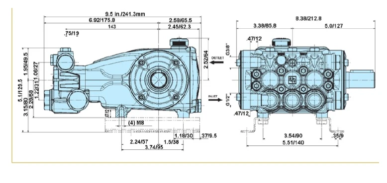
Dimensions and connections
| Dimension | Value |
|---|---|
| Overall envelope | 9.5 × 8.38 × 5.1 inches |
| Shaft | 0.945 inch / 24 mm, keyed |
| Mounting | Four M8 points; optional pump feet |
| Inlet | G ½ · ½-14 BSP-F |
| Discharge | G ⅜ · ⅜-19 BSP-F |
Parts, repair kits & torque
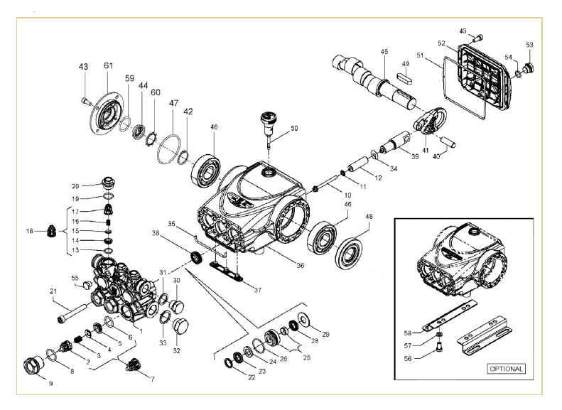
Use the exploded-view item number and exact pump bore.
Model-specific parts
The original parts drawing and manufacturer part numbers are retained for identification. Confirm the model and kit with IHC before ordering; a manufacturer number is not necessarily an IHC catalog number.
| Item / part | EP1812S17 | EP1508S34 |
|---|---|---|
| 12 · Plunger | 58040209 · 18 × 42 mm | 58040109 · 15 × 42 mm |
| 22 · Head ring | 63101151 | 63101051 |
| 23 · High-pressure packing | 90265300 | 90261100 |
| 24 · Anti-extrusion ring | 90511150 | 90508990 |
| 25 · Intermediate ring | 58605801 | 58605701 |
| 28 · Low-pressure seal | 90265000 | 90260800 |
| 29 · Support ring | 58210770 | 58210770 |
| 45 · Crankshaft | 63021665 · 12 mm | 63020865 · 8 mm |
Common manufacturer parts
The source also lists assembled oil-level indicator 53150001 without screws and O-ring. Use page 6 of the PDF for the original quantities and dimensional descriptions.
| Item | Part number | Description |
|---|---|---|
| 2 | 36202551 | Valve cage |
| 3 | 94737600 | Valve spring |
| 5 | 36200366 | Valve seat |
| 6 | 701115 | O-ring |
| 7 | 36711501 | Valve assembly |
| 8 | 701002 | O-ring |
| 9 | 98222600 | M24 valve cap |
| 10 | 99169000 | M5 × 55 plunger bolt |
| 11 | 96690500 | Washer |
| 13 | 701014 | O-ring |
| 14 | 36211366 | Outlet valve seat |
| 15 | 36211276 | Outlet valve poppet |
| 16 | 94733300 | Outlet spring |
| 17 | 36211151 | Outlet cage guide |
| 18 | 36719301 | Complete outlet valve |
| 19 | 701016 | O-ring |
| 20 | 98213700 | M18 outlet valve cap |
| 21 | 99317500 | M8 × 60 head screw |
| 26 | 701023 | O-ring |
| 30 | 98210000 | ⅜-inch plug |
| 31 | 96738000 | Gasket |
| 32 | 98217600 | ½-inch BSP plug |
| 33 | 96751400 | Gasket |
| 34 | 96698000 | Washer |
| 35 | 58210582 | Gasket |
| 36 | 58010022 | Crankcase |
| 37 | 58210451 | Drip cover |
| 38 | 90156550 | Oil seal |
| 39 | 58050066 | Piston guide |
| 40 | 97734000 | Piston pin |
| 41 | 58030022 | Connecting rod |
| 44 | 53210851 | Oil-level indicator |
| 46 | 91833100 | Bearing |
| 47 | 90389800 | O-ring |
| 48 | 90164100 | Oil seal |
| 49 | 91489200 | Key |
| 50 | 98210500 | Dipstick |
| 51 | 90392550 | O-ring |
| 52 | 58160022 | Rear cover |
| 53 | 98204100 | ¼-inch plug |
| 54 | 701013 | O-ring |
| 55 | 98196600 | ⅛-inch plug |
| 56 | 99303700 | Optional foot screw |
| 57 | 96701600 | Optional foot washer |
| 58 | 50200074 | Optional foot |
| 60 | 90067100 | Stop ring |
| 61 | 58150122 | Side cover |
Repair-kit compatibility
| Kit | Contents / coverage | Model |
|---|---|---|
| K269 | Valve kit; six valves / three cylinders | Both |
| K270 | Valve caps and O-rings | Both |
| K271 | Three oil seals | Both |
| K274 | Packing/ring set, three cylinders | EP1812S17 |
| K277 | Packing/ring set, one cylinder; three needed for full pump | EP1812S17 |
| K229 | Hot-service seal kit | EP1812S17 |
| K273 | Packing/ring set, three cylinders | EP1508S34 |
| K276 | Packing/ring set, one cylinder; three needed for full pump | EP1508S34 |
| K276H / K312H | Hot-service kits listed in source | EP1508S34 |
Fastener torque and head sequence
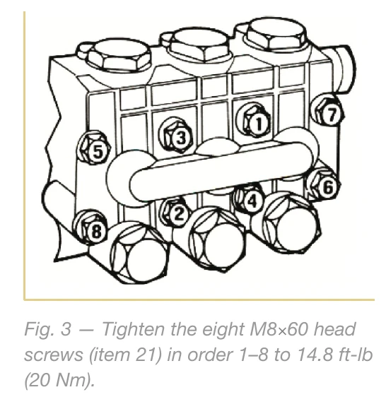
The source specifies a 20% torque reduction on lubricated threads and identifies thread sealant for items 30 and 55. Follow the applicable manufacturer instructions for the installed part. Tighten the eight head screws in the illustrated 1–8 sequence.
| Item / fastener | ft-lb | N·m |
|---|---|---|
| 9 · M24 valve cap | 96 | 130 |
| 10 · M5 plunger bolt | 4.5 | 6 |
| 20 · M18 outlet valve cap | 44.3 | 60 |
| 21 · M8 head screw | 14.8 | 20 |
| 30 · ⅜-inch plug | 30 | 40 |
| 32 · ½-inch BSP plug | 30 | 40 |
| 43 · M6 cover screw | 7.4 | 10 |
| 53 · ¼-inch plug | 14.8 | 20 |
| 55 · ⅛-inch plug | 9.6 | 13 |
| 56 · Foot screw | 14.8 | 20 |
Lubrication & service
Inspect the oil, drive, valves, plungers and packing stacks.
Oil and maintenance intervals
Use the specified 15 oz of General Pump Series 100 / appropriate 30-weight non-detergent pump oil. Check the dipstick or level indicator with the pump stopped. Change warm oil after the first 50 hours and maintain the station’s oil, filter and belt schedule.
The EP document contains inconsistent routine oil intervals: 500 hours in its schedule, three months in its oil section and a separate 300-hour statement. Confirm the installed pump’s interval with IHC or its current manufacturer instructions. Do not use the longest interval by default.
Milky oil can result from condensation or failed water seals. Milky, foamy oil with packing leakage calls for stopping the pump and investigating the seals and plungers.
Manifold and check valves
- Isolate the equipment and confirm zero pressure. Remove the eight M8 × 60 head screws and slide the manifold straight off the plungers with care. A light rawhide-mallet tap may help separate it.
- Remove the valve caps and lift the valve assemblies. Inspect spring closure, debris, cracked plastic cages and all O-rings.
- Clean the isolated head and valve cavities. Keep track of the O-rings beneath the valves; replace damaged seals and worn assemblies.
- Install the matched O-rings and valves. Refit inlet and outlet caps to their different specified torques.
- Slide the manifold straight onto the plungers. Tighten the eight head screws in sequence to the applicable specification.
Ceramic plunger replacement
EP1812S17 uses 18 mm plunger 58040209; EP1508S34 uses 15 mm plunger 58040109. Replace scored, cracked, damaged or worn plungers.
- Remove the isolated manifold head, plunger bolt and plunger.
- Reinstall the slinger washer if it comes away.
- Fit the new O-ring and backup ring on the bolt. Lightly lubricate the outside of the O-ring with compatible grease.
- Press the bolt into the new plunger and reassemble. The source gives 4.5 ft-lb / 6 N·m for the plunger bolt, subject to its thread-condition instructions.
V-ring packing replacement
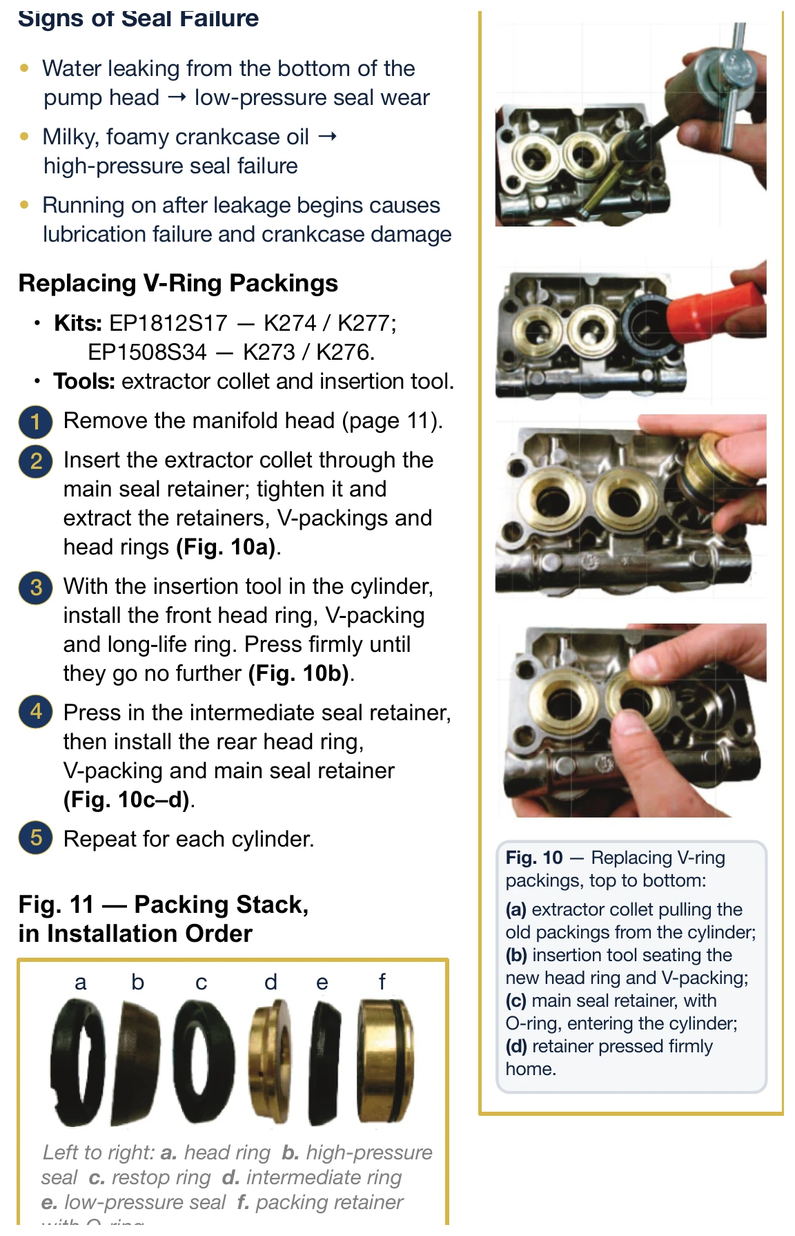
The source calls for packing service at 2,000–2,500 hours or the first sign of leakage. Use the correct bore-specific kit and the extraction/insertion tools.
- Remove the isolated manifold head.
- Extract the main retainers, V-packings and head rings with the correct collet.
- Install the front head ring, V-packing and long-life ring with the insertion tool.
- Press in the intermediate retainer, then install the rear head ring, V-packing and main retainer.
- Repeat for all cylinders; inspect plungers and replace water-contaminated oil before testing.
Hydraulic & mechanical faults
Investigate the cause before running a pump with abnormal pressure, leakage or noise.
Pump symptoms and checks
Pulsation or rough running
- Possible cause
- Stuck or dirty valves, inlet restrictions or air entering the inlet.
- What to check
- Stop and inspect supply, filtration, inlet seals and check valves; service the affected parts.
Low pressure
- Possible cause
- Belt slip, worn nozzles or packings, restricted supply, a leaking line or regulating-valve problem.
- What to check
- Check the water and drive system first, then inspect the isolated valves and packings.
Water leaking below the manifold
- Possible cause
- Worn packing or a cracked plunger.
- What to check
- Stop the pump and inspect the seals and plungers.
Oil leak between crankcase and head
- Possible cause
- Worn piston-rod seals or plunger-retainer O-rings.
- What to check
- Replace the affected seals and inspect the rod surfaces.
Oil leak at crankshaft or rear cover
- Possible cause
- Damaged shaft seal, bearing, cover, drain plug or sight-glass seal.
- What to check
- Inspect the leak source and replace damaged seals or mechanical parts.
Excessive pulley or shaft play
- Possible cause
- Worn bearing, potentially from excessive belt tension.
- What to check
- Inspect bearing and drive alignment; replace worn parts and correct tension.
Water in crankcase oil
- Possible cause
- Condensation, worn packings/O-rings or a cracked plunger.
- What to check
- Investigate before operation; repair leaks and change contaminated oil.
Loud knocking
- Possible cause
- Loose pulley/key, damaged rod or bearing, or a sticking valve.
- What to check
- Stop operation and inspect the drive and internal components.
Repeated packing failure
- Possible cause
- Damaged plungers, abrasive water, excessive inlet conditions, overpressure or dry running.
- What to check
- Correct supply and filtration, inspect plungers and stay within the matched pump’s ratings.
Parts & references
Continue with related guides, parts and the original PDF.
Related parts
Original & related PDFs
This web guide is adapted from the IHC reference linked below. The original PDF retains its diagrams, document revision and printable layout.