Before service: Isolate power and water and verify zero pressure. Read the safety instructions →
Controller & connections
Identify the controller and the devices it coordinates.
Before inspection or service
ZEN-10C1AR-A-V2 specifications
The pump-station control circuits also use 24 VAC for the humidistat and fan relays. That control signal is not the supply rating of this AC-powered PLC model. Confirm the installed station schematic before testing.
| Item | Specification |
|---|---|
| Power supply | 100–240 VAC nominal, 85–264 VAC range · 50/60 Hz |
| Consumption | 8 VA maximum |
| Inputs / outputs | 6 digital inputs and 4 relay outputs; source rating 8 A at 250 VAC / 24 VDC |
| Display | Backlit LCD · 12 characters × 4 lines |
| Program | Ladder logic; timers, counters and comparators |
| Mounting | DIN rail or surface · approximately 70 × 90 × 56 mm |
| Environment | 0–55°C · 10–90% RH, non-condensing |
| Other features | Clock/calendar and EEPROM backup |
What the PLC controls
| Component | Role |
|---|---|
| Humidistat / cube relay | 24 VAC humidity call becomes the start input. |
| Q0 / fans | Fan relay control; immediate start and delayed stop. |
| Q1 / pump circuit | Motor contactor, inlet solenoid, EDV coil and green RUN indicator. |
| HPS / Input 1 | Pressure-proven signal; failure to prove pressure triggers shutdown. |
| Q2 / red FAULT | Pressure fault indication. |
| Q3 / amber MAINT | 500 pump-hour maintenance reminder; reset after service with buttons 3 + 4. |
| Hour meter | Records pump run time for maintenance planning. |
Sequence & screen display
Read the startup, pressure proof and shutdown stages.
From humidity call to normal operation
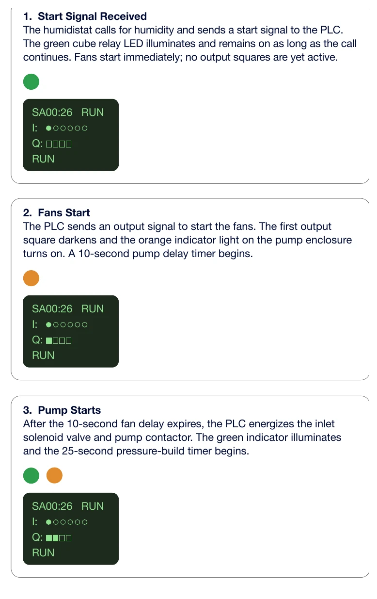
- The humidistat calls and the cube-relay LED lights. The start signal remains present while demand continues.
- The fans start immediately. The first output square darkens, the orange fan indicator lights and the 10-second pump delay begins.
- At the end of the delay, the pump circuit starts, the green RUN indicator lights and the 25-second pressure timer begins.
- While waiting for pressure proof, the red indicator is also on. Once pressure is proven, red clears and the pump continues near 1,000 psi.
Fault shutdown and normal shutdown
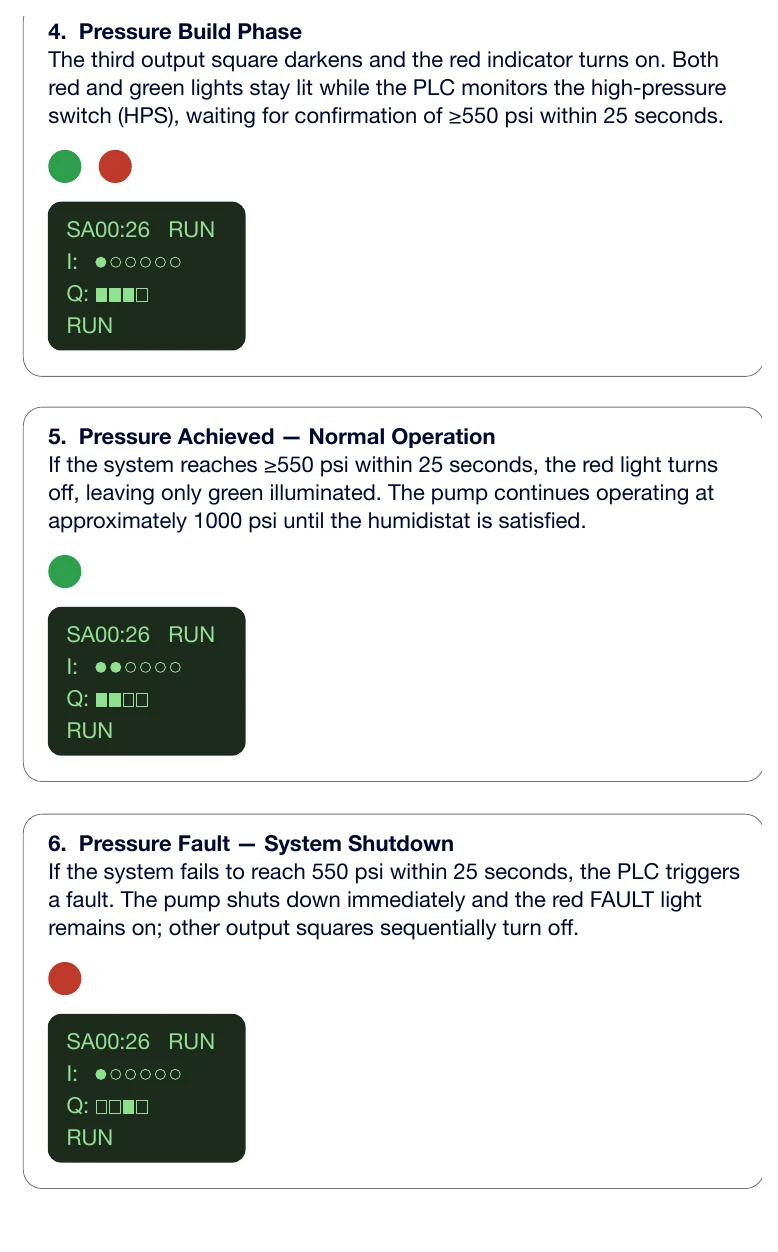
Failure to prove pressure in time produces a latched red FAULT condition and stops the system. A cube-relay LED can remain lit because the humidistat is still calling; this does not mean the pump is being powered. Correct the pressure problem before cycling the start signal to reset.
During normal shutdown, humidity demand ends, the pump stops and the EDV opens. Fans continue for 10 seconds before stopping.
Timers & maintenance
Check the two operating delays and reset completed maintenance.
T1 and T2 timer settings
T1 delays pump start after the fans start. T2 delays fan stop after the pump stops. Both are normally 10 seconds. Q0 has no startup delay; Q1 has no shutdown delay.
- Press OK, select Parameter using the down arrow, then press OK.
- Select the required timer. If necessary, press OK so the timer number blinks, select T1 or T2 with the up/down arrows, and confirm with OK.
- Move left to the timer value and press OK. Move between digits with the left arrow; change the value with up/down arrows, then press OK.
- Press ESC twice to return to the normal screen. Observe a complete cycle to verify the setting.
500-hour reminder and fault counters
Perform the oil, filter, belt and pump-head checks when the amber maintenance indicator comes on. Then press buttons 3 and 4 together until the amber light goes off. Record the hour-meter reading and completed work.
Press ESC from the normal PLC operating screen to view fault counters. A reset does not repair the condition that caused a fault.
Troubleshooting
Use the indicators to find the affected control or water circuit.
Controller symptoms and checks
Pump will not start
- Possible cause
- No humidity call, missing start signal or a latched fault.
- What to check
- Check the set point, cube-relay LED and red FAULT indicator. Correct a fault before resetting.
Red light stays on or system stops after 25 seconds
- Possible cause
- Pressure is not proven, or the HPS signal is missing.
- What to check
- Check water supply, filters, leaks and actual gauge pressure; then have a qualified technician verify the HPS connection.
Fans do not start
- Possible cause
- Missing fan-control signal, remote contactor failure or wiring fault.
- What to check
- Check the fan-control circuit and relay using the station schematic.
Fans start but pump does not
- Possible cause
- T1 setting, pump output or pump circuit problem.
- What to check
- Observe the startup screen and verify T1, Output 1 and the pump contactor circuit.
Pump runs with low pressure or no mist
- Possible cause
- Inlet valve not opening, restricted supply or a hydraulic fault.
- What to check
- Check the valve command, inlet water and pressure system.
Nozzles drip after shutdown
- Possible cause
- EDV is not opening or its drain is restricted.
- What to check
- Check shutdown pressure and the drain-valve circuit.
Intermittent starting or continuous running
- Possible cause
- Unstable or stuck humidity call, or loose/shorted control wiring.
- What to check
- Observe the cube-relay LED and check the humidistat and its connections.
Blank or frozen PLC display
- Possible cause
- Controller supply or internal fault.
- What to check
- Have a qualified technician verify the installed PLC’s rated AC supply and fuse protection. Do not confuse its supply with the 24 VAC field-control circuit.
Maintenance reminder will not clear
- Possible cause
- Reset incomplete or controller setting issue.
- What to check
- After completing maintenance, press buttons 3 + 4 together; consult IHC if the indicator remains on.
Parts & references
Continue with related guides, parts and the original PDF.
Original & related PDFs
This web guide is adapted from the IHC reference linked below. The original PDF retains its diagrams, document revision and printable layout.