Before service: Isolate power and water and verify zero pressure. Read the safety instructions →
Identification & ratings
Use the correct pressure-switch version and distinguish its ratings.
Before inspection or service
Pressure proving protects the pump
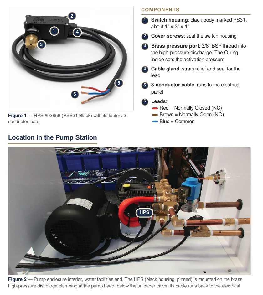
The HPS is mounted on the pump’s high-pressure discharge and sends a pressure-proven signal to PLC Input 1. The controller shuts the system down when pressure is not proven within its allowed time.
Use part 93656, the PSS31 Black version (housing marked PS31). The component reference lists approximately 580 psi activation for the black O-ring switch and describes the FanMist PLC requirement as 550 psi within 25 seconds. These are distinct descriptions in the source; 550 psi on the gauge alone does not prove that the switch has closed.
Switch ratings and color codes
| Item | Specification |
|---|---|
| Correct part | 93656 · PSS31 Black |
| Activation | Approximately 580 psi · black O-ring |
| Other versions | Yellow 115 psi; blue 210 psi; red 360 psi — not the FanMist replacement |
| Connection | ⅜-inch BSP brass pressure port |
| Contacts | SPDT · 250 V, 15 A |
| Leads | Blue: common · brown: normally open · red: normally closed |
| Maximum switch rating | 4,100 psi; this does not change FanMist’s 1,000 psi operating limit |
| Approximate body size | 1 × 3 × 1 inches |
Location and system pressure points
Operation & wiring
Follow the proof signal from the switch to the PLC.
Normal run and fault behavior
- Ten seconds after the fans start, Output 1 starts the pump and the PLC begins its 25-second pressure timer. Red and green indicators are on while pressure builds.
- When the HPS closes, Input 1 receives the proof signal. The red indicator goes out and the green RUN indicator stays on.
- On normal shutdown the pump stops, the EDV releases pressure and the HPS reopens. An open switch during normal idle is not a fault.
- If pressure is not proven in time, or is lost during operation, the controller faults off. Correct the cause and inspect for leaks before attempting a reset.
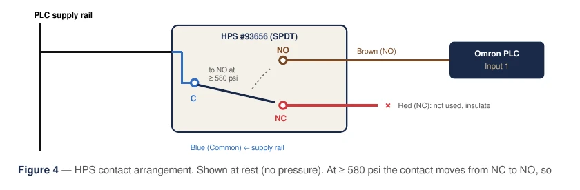
Common and normally open connections
Match the original station connections when replacing the switch. The source lists Tb at 25 seconds and an initial-startup allowance of 60 seconds for filling empty lines. Have IHC confirm startup settings rather than extending a timer to conceal a pressure fault.
| Lead | Use |
|---|---|
| Blue · Common | PLC supply side |
| Brown · Normally open | PLC Input 1; closes when pressure is proven |
| Red · Normally closed | Unused; insulate the end |
Replacement & diagnosis
Correct the cause of a pressure fault and test the replacement safely.
Replacement and reset
- Stop the pump, lock out power, isolate water and confirm zero pressure after the EDV opens.
- Record the blue and brown lead connections and the insulated red lead before disconnecting them.
- Remove the switch from the ⅜-inch BSP port. Fit the correct 93656 black version, with its O-ring and appropriate thread sealing.
- Reconnect as recorded, insulate the unused lead and close the equipment. Restore water and power for a controlled test.
- After correcting the underlying fault, cycle the start signal or pump switch off and on. Confirm normal pressure, no port leaks and the red light clearing within the normal pressure-proving interval.
Pressure-fault checks
Red FAULT and little or no pressure
- Possible cause
- Leak, low water supply, blocked filter or inlet valve problem.
- What to check
- Inspect the supply, filter, valve and lines. Correct the problem before resetting.
Pressure rises slowly
- Possible cause
- Restricted incoming flow or leaking tubing/fittings.
- What to check
- Check supply capacity, filter and inlet-solenoid operation. Inspect Slip-Lok fittings and tube condition.
Gauge shows pressure but red light remains on
- Possible cause
- No proof signal, wrong switch version, bad connection or failed switch.
- What to check
- With power isolated, check blue/common and brown/NO connections and the black 93656 part identity. Have a qualified technician verify the proof signal.
Fault during initial filling
- Possible cause
- High-pressure distribution lines are not filled.
- What to check
- Follow the installation startup procedure; ask IHC to confirm startup settings. Do not bypass the HPS.
Fault will not reset
- Possible cause
- Cause remains active or start signal has not been cycled.
- What to check
- Use ESC to view PLC fault counters, correct the cause, then cycle the start signal off and on.
Parts & references
Continue with related guides, parts and the original PDF.
Related parts
Original & related PDFs
This web guide is adapted from the IHC reference linked below. The original PDF retains its diagrams, document revision and printable layout.