Meet FanMist
High-velocity air and fine water atomization, working together to put moisture where your production needs it.
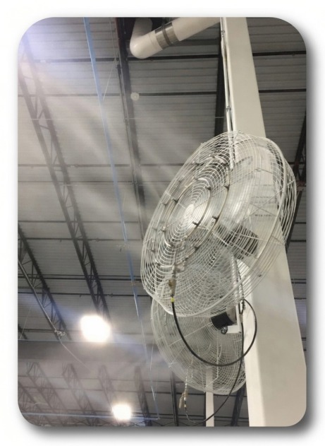 FAN-ASSISTED ATOMIZATION AT 1,000 PSI
From water.
To fine mist.
To balanced plant air.
A high-pressure pump sends water through fine misting nozzles on a stainless steel ring. Fan airflow carries the droplets into an unobstructed air space, accelerating evaporation.
A zone humidity controller monitors conditions and signals the pump-station PLC. The PLC coordinates the fan, pump, and valve sequence as humidity is needed.
Plan a system with IHCA controlled start. A clean stop.
Current FanMist stations give the fans a ten-second head start before the pump delivers water. At the humidity set point, the pump stops and the fans continue for ten seconds to clear the remaining mist. The electric drain valve releases line pressure at shutdown.
Earlier stations may use a different sequence. Match the guide to your equipment, or contact IHC for help identifying the configuration.
Fan & pump delay guide · PDFSense demand
The zone humidistat signals when relative humidity falls below its set point.
Establish airflow
Fans start first so the mist enters moving air.
Deliver and monitor
The pump supplies the nozzles while the PLC monitors the pressure safety input.
Clear the mist
The pump stops, line pressure releases, and the fans finish their run-on period.
The pieces behind the performance.
Pump station
General Pump EP Series pumps provide high-pressure water for atomization. The pump station brings the pump, motor, valves, and controls together.
Fans & mist rings
High-velocity industrial fans and matched stainless steel mist rings distribute moisture. Fan placement and clear plume space are part of system design.
Zone controls
Humidity controllers signal demand in each zone. The PLC sequences system operation and coordinates safety inputs.
Three inputs.
A sound starting point.
System sizing begins with how much air is in your building, how quickly it is replaced, and the conditions you need to maintain.
Explore the load calculator guidesSpace
Length, width, and ceiling height for each area.
Air exchange
Process exhaust and makeup-air flow, including winter outdoor-air settings.
Target conditions
Desired relative humidity at your winter indoor temperature.
Service information close at hand.
The PLC tracks pump run hours and signals routine service with its amber maintenance light. The service guide covers the first oil change at 50 hours, recurring 500-hour checks, annual service, and seasonal care.
Maintenance schedule & procedures · PDFIdentify the component
Use labeled pump station views and the part-number index to find the right component before ordering.
Pump station views & parts · PDFStart with the symptom
The troubleshooting guide groups checks by component and points to the supporting technical documents.
Troubleshooting by part · PDFPlan the water supply, too.
Filtration and appropriate treatment help manage suspended particles,
mineral scale, and dust from dissolved solids.