Before service: Isolate power and water and verify zero pressure. Read the safety instructions →
Sequence & timing
Understand why airflow leads and follows the pump.
Before inspection or service
Air before water; airflow after shutdown
Current FanMist stations start fans immediately on a humidity call and start the pump 10 seconds later. When demand ends, the pump stops first and fans continue for 10 seconds.
Some earlier stations started and stopped fans and pump together. Separating the outputs allows the first mist to enter moving air and the last mist to clear as the EDV depressurizes the line.
The five operating stages
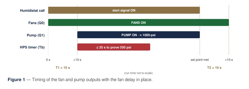
| Stage | Fans / pump |
|---|---|
| Idle | Q0 and Q1 open; both off. |
| Humidity call | Q0 closes immediately; fans on; T1 begins. |
| After 10 seconds | Q1 closes; pump circuit on; Tb pressure timer begins. |
| Set point satisfied | Q1 opens immediately; pump off; EDV opens; T2 begins. |
| After 10 more seconds | Q0 opens; fans stop. |
Outputs and factory timers
| Output / timer | Function |
|---|---|
| Q0 | 24 VAC fan-control circuit; immediate start and T2 delayed stop. |
| Q1 | Inlet solenoid, EDV, motor contactor and green RUN light; T1 delayed start. |
| Q2 | Red pressure FAULT indicator. |
| Q3 | Amber 500-hour MAINT indicator. |
| T1 / T2 | 10 seconds each. |
| Tb | 25 seconds to prove pressure during normal operation. |
Earlier-station conversion
Use the illustrated procedure only for the matching earlier wiring arrangement.
Separate the Q0 and Q1 circuits
This conversion applies to the earlier station arrangement shown in the reference. A qualified electrician should compare the installed wiring with the diagram before making changes. Keep power locked out and the system depressurized throughout the conversion.
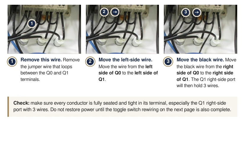
- Remove the jumper linking Q0 and Q1.
- Move the wire from the left side of Q0 to the left side of Q1.
- Move the black wire from the right side of Q0 to the right side of Q1. The illustrated Q1 right terminal then has three conductors; verify that the terminal is suitable and all connections are secure.
- Complete the fan-toggle conversion before restoring power.
Fan-only toggle conversion
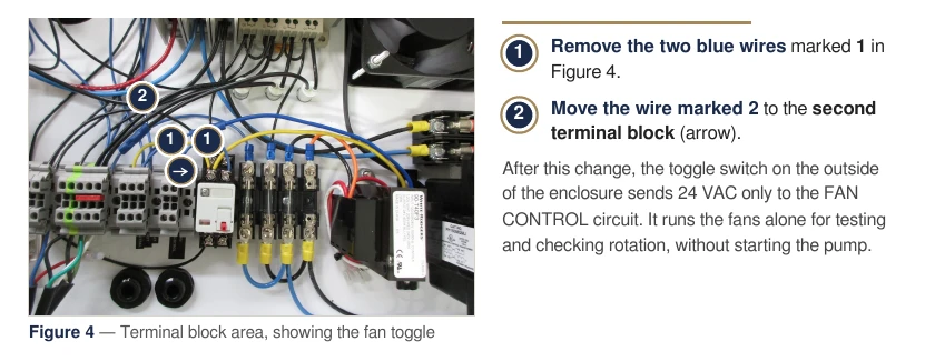
On the illustrated terminal-block arrangement, remove the two blue wires marked 1. Move the wire marked 2 to the second terminal block indicated by the arrow. This makes the override feed the FAN CONTROL circuit only.
The numbered wire identities depend on this diagram. Do not apply the moves to a different station configuration without IHC confirmation.
Testing & troubleshooting
Confirm independent fan control and both ten-second delays.
Post-conversion test
- With wiring complete, covers and guards restored, restore water and power.
- Switch fan override on: fans should run with the pump off. Switch it off.
- Raise the humidistat above room RH. Fans should start immediately and the pump approximately 10 seconds later.
- Confirm normal operating pressure and pressure proof within the normal timer interval.
- Lower the set point below current RH. The pump should stop immediately, the EDV should release pressure, and fans should stop 10 seconds later.
- Return the humidistat to the intended set point.
Conversion faults
| Symptom | Check |
|---|---|
| Fans and pump still start together | Q0/Q1 jumper and circuit placement. |
| Pump starts but fans do not | Q0 fan circuit and 24 VAC fan-control run. |
| Fans start but pump does not | Q1 connections, T1 and cube-relay start signal. |
| Delay differs from ten seconds | Verify T1 and T2. |
| Toggle starts the pump or does nothing | Compare the terminal-block conversion with the correct station diagram. |
Parts & references
Continue with related guides, parts and the original PDF.
Original & related PDFs
This web guide is adapted from the IHC reference linked below. The original PDF retains its diagrams, document revision and printable layout.