Before service: Isolate power and water and verify zero pressure. Read the safety instructions →
Power & field wiring
Separate plant-power circuits from 24 VAC controls.
Before inspection or service
Four field wiring runs
The station’s internal wiring is factory assembled. A qualified electrician supplies plant power to the pump and fan relay contacts, and connects the humidistat and fan-relay control circuits.
The 24 VAC fan-control signal switches a relay; it does not supply the fan motors. Match all line-power connections to the installed nameplates and station schematic.
| Run | Connection |
|---|---|
| A · Pump power | Dedicated branch circuit to the station; 115/230 V single phase or 230/480 V three phase as ordered. |
| B · Humidistat | Three-wire 18 AWG: station NEUTRAL / HOT / RELAY to HRO20. |
| C · Fan control | Two-wire 18 AWG: FAN CONTROL terminals to relay coil. |
| D · Fan power | Plant power through relay contacts to fan motors. |
Station entry and internal protection
The reference specifies a dedicated 20 A pump branch circuit, strain reliefs on both sides of wiring entries and an internal 10 A breaker. Single-phase stations use the specified supply cord; three-phase stations are hard-wired.
Internal fuse and transformer arrangements vary. The source shows a 1.5 A fuse for the 115 V configuration and two 0.6 A fuses with the 480 V arrangement. A 93301, 150 W transformer steps 480 V down to 230 V where fitted. Verify the exact station before replacing protective devices.
Humidistat & fan relays
Use the correct terminal and relay model connections.
HRO20 humidistat terminals
Other TB1 positions are unused in the illustrated FanMist application. Mount the controller at an accessible height in a representative location, away from direct mist and unusual drafts. One controller operates each station.
The controller offers a 10–90% RH setting range. To adjust the set point, press both arrow buttons simultaneously twice, adjust using the arrows and allow the display to return. Confirm the installed controller’s dead-band configuration; reference documents give differing values.
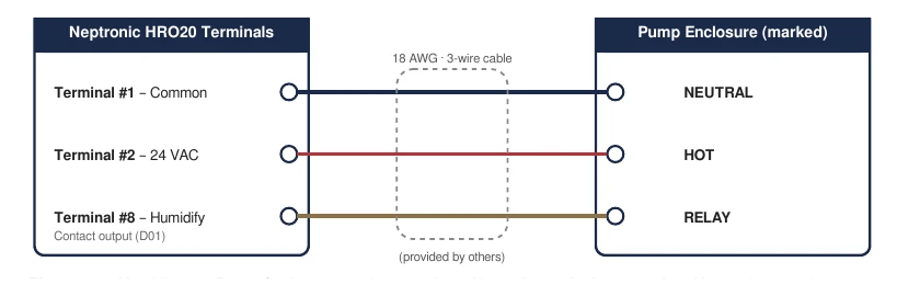
| HRO20 TB1 | Station terminal | Function |
|---|---|---|
| 1 | NEUTRAL | Common |
| 2 | HOT | 24 VAC supply |
| 8 | RELAY | Humidify call |
Single-phase and three-phase fan relays
The source describes RIB2401B for 1–2 single-phase fans and RIB243P for 1–8 three-phase fans. Final selection depends on actual motor load and the relay’s applicable motor rating. Verify lead colors against the installed relay label; wire colors are model-specific.
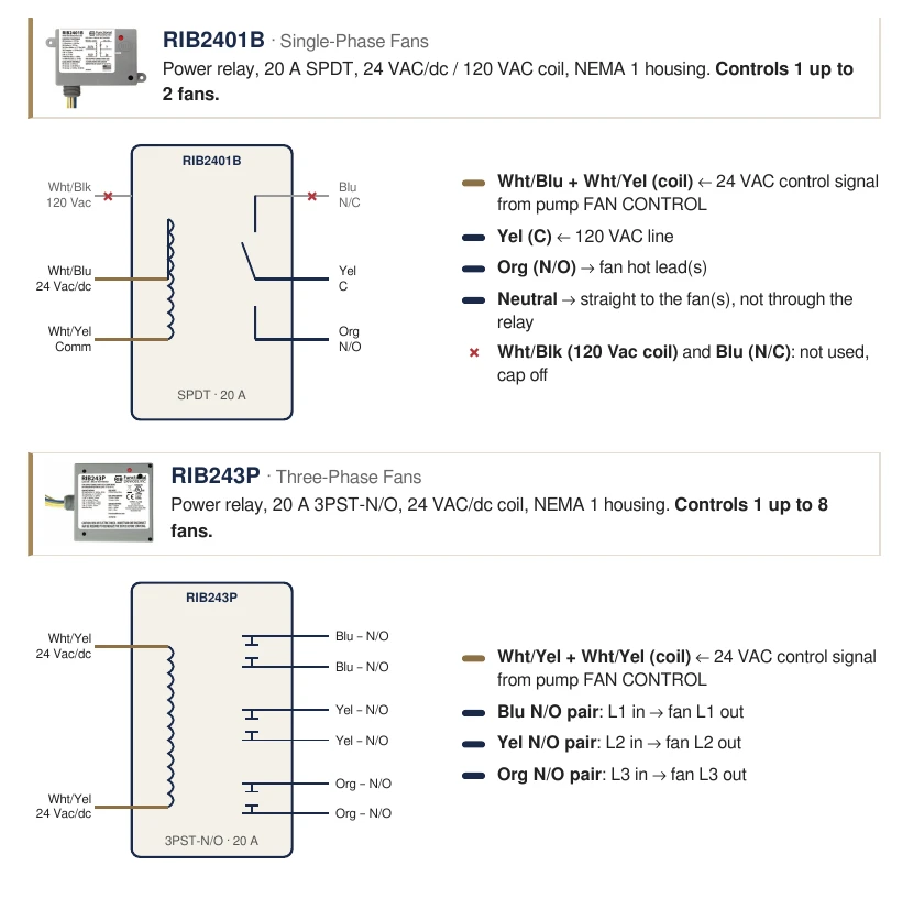
| Model | Control coil | Switched power |
|---|---|---|
| RIB2401B · SPDT | White/blue and white/yellow: 24 VAC control | Yellow common → orange normally open. Blue NC and unused white/black 120 V coil lead are separately insulated. |
| RIB243P · 3PST-NO | Two white/yellow wires: 24 VAC control | Blue pair L1, yellow pair L2, orange pair L3. |
Fan motor wiring and rotation
- Match plant voltage and phase to the fan nameplate. Have a qualified electrician make any required connection changes.
- Fit a local fan disconnect and a drip loop below the motor enclosure.
- Mount the motor capacitor on top where applicable; remove the specified lower drain plugs.
- Use fan override to confirm that air blows forward through the mist ring. Correct rotation before introducing mist.
Station schematics
Open the original electrical drawings for the matching supply configuration.
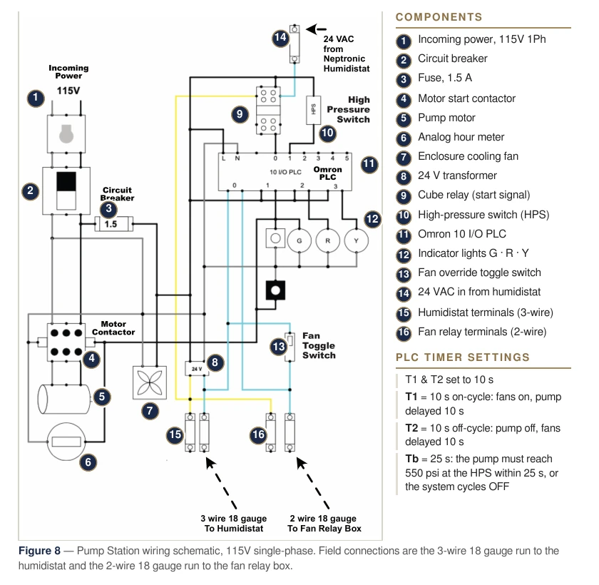
115 V / 230 V single-phase schematic
The original drawing identifies supply protection, transformers, PLC, switches, indicators, humidistat, fan control, inlet solenoid, EDV and motor contactor. For 230 V, the source notes a blue conductor in place of the 115 V white conductor and a double fuse arrangement.
Use the matching as-built station drawing for field work. The image can be opened at its full resolution.
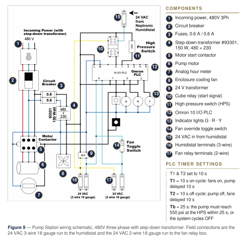
480 V / 230 V three-phase schematic
The 480 V arrangement includes the 93301 step-down transformer. The source’s 230 V three-phase variant omits that additional transformer. Confirm the installed enclosure, supply and control components before using either arrangement.
PLC & operating sequence
Trace a humidity call through the controller and its outputs.
PLC input/output map
The inlet and EDV coils must match their supply: the inlet reference lists 93368 for 115 V and 93596 for 230 V. The EDV closes when energized and opens when de-energized. The inlet valve does the opposite.
| Terminal | Connection |
|---|---|
| L / N | Fused PLC supply; match controller model |
| Input 0 | Cube relay contact: humidistat start signal |
| Input 1 | HPS pressure-proof contact |
| Output 0 | 24 VAC to FAN CONTROL |
| Output 1 | Inlet valve, EDV, motor contactor and green RUN light |
| Output 2 | Red FAULT light |
| Output 3 | Amber MAINT light after 500 run hours |
Normal operating cycle
The wiring reference describes a 550 psi pressure-proof condition within 25 seconds. The black HPS component reference lists a nominal 580 psi switch activation. These are distinct source descriptions, not an instruction to adjust the sealed switch.
- Idle: fans and pump off; inlet valve closed; EDV open.
- Humidity call: Input 0 starts the cycle; Output 0 starts fans and T1 starts counting.
- After 10 seconds: Output 1 starts the pump, opens the inlet and closes the EDV. Pressure proving begins.
- With pressure proven: red FAULT indication clears; the station operates at approximately 1,000 psi.
- Demand ends: Output 1 drops out; the pump stops, inlet closes and EDV opens.
- After 10 more seconds: Output 0 drops out and fans stop.
Startup & fault checks
Verify the completed wiring with the system safely reassembled.
Electrical startup checklist
- Correct pump branch supply, grounded connections and all strain reliefs installed.
- HRO20 terminals 1 / 2 / 8 connected to NEUTRAL / HOT / RELAY.
- FAN CONTROL connected to the relay coil; plant power connected through the relay contacts.
- Each fan has its local switch and drip loop; rotation verified with override.
- With water and mechanical installation ready, a test humidity call starts fans before the pump.
- Pressure reaches normal operation within the configured pressure-proof window.
- Demand removal stops the pump, releases line pressure and runs the fans for the final 10 seconds.
- Return the humidistat to its operating set point.
Electrical troubleshooting
Pump will not start
- Possible cause
- No humidistat call or missing cube-relay signal.
- What to check
- Verify set point and terminals 1 / 2 / 8. A qualified technician can check the cube-relay LED and Input 0.
Fans do not run
- Possible cause
- Missing control voltage or fan plant power.
- What to check
- Check the relay control run, supply and override function using the matching diagram.
Fan turns backward
- Possible cause
- Motor connection does not match the required rotation.
- What to check
- Have a qualified electrician correct the nameplate wiring and retest.
Whole station is dead
- Possible cause
- Branch breaker, internal breaker or station switch is off.
- What to check
- Investigate the reason for a trip before restoring power; inspect the correct fuse circuit.
Red FAULT light and pump shutdown
- Possible cause
- Pressure has not been proven.
- What to check
- Correct water-supply, filter, inlet-valve or leakage problems before resetting.
Nozzles drip after stopping
- Possible cause
- EDV not opening or drain restriction.
- What to check
- Inspect the EDV, connector, coil and drain path after isolating and depressurizing.
Parts & references
Continue with related guides, parts and the original PDF.
Original & related PDFs
This web guide is adapted from the IHC reference linked below. The original PDF retains its diagrams, document revision and printable layout.