Before service: Isolate power and water and verify zero pressure. Read the safety instructions →
Models & performance
Compare fan models and match water output to the available airflow.
Before inspection or service
Fan-assisted evaporation
The 36-inch, ½ HP basket fan moves approximately 10,000 CFM through the face-mounted mist ring. The IHC design uses an unobstructed plume approximately 4 feet in diameter and 22 feet long, above equipment and occupied work areas.
The fan supplies moving, unsaturated air to the fine droplets. It starts before the pump and continues after it stops, so atomized water enters an established air stream.
36-inch models and 24-inch alternatives
These are the fan technical document’s ratings. Wire and protect each installed motor according to its nameplate. The 36-inch single-phase fan also has -C115 and -C230 cord versions; the three-phase version is hard-wired.
Both 36-inch models weigh approximately 63 lb, have a white powder-coat finish, a hinged front guard and a supplied 30-inch bracket. The source lists sound at 68 dB measured 10–15 feet away.
| Model | Supply | Rated airflow | Speed / current |
|---|---|---|---|
| VBS36A | 115/230 V · single phase | 10,050 CFM | 844 RPM · 6.2/3.1 A |
| VBS36CF | 208–230/460 V · three phase | 10,000 CFM | 846 RPM · 2.6/1.31 A |
| VBS24 / VBS24-110 | 115/230 V · single phase; cord variant available | 5,300 CFM | 4.8/2.4 A |
| VBS243A | 230/460 V · three phase | 4,250 CFM | 2.6/1.3 A |
Loading ratio and ring selection
The reference calls for a loading ratio above 75. A 36-inch fan with a 27-inch, 14-port ring and 7.94N nozzles supplies 111.16 lb/hr, giving approximately 90 CFM per lb/hr at 10,000 CFM.
A 24-inch fan uses an 18-inch, eight-port ring. Recalculate using the actual fan rating: the three-phase 24-inch fan has less airflow than the single-phase version. Do not apply the 5,300 CFM example to a 4,250 CFM motor.
Placement & mounting
Provide plume clearance, secure mounting and correct motor orientation.
Choose the location and direction
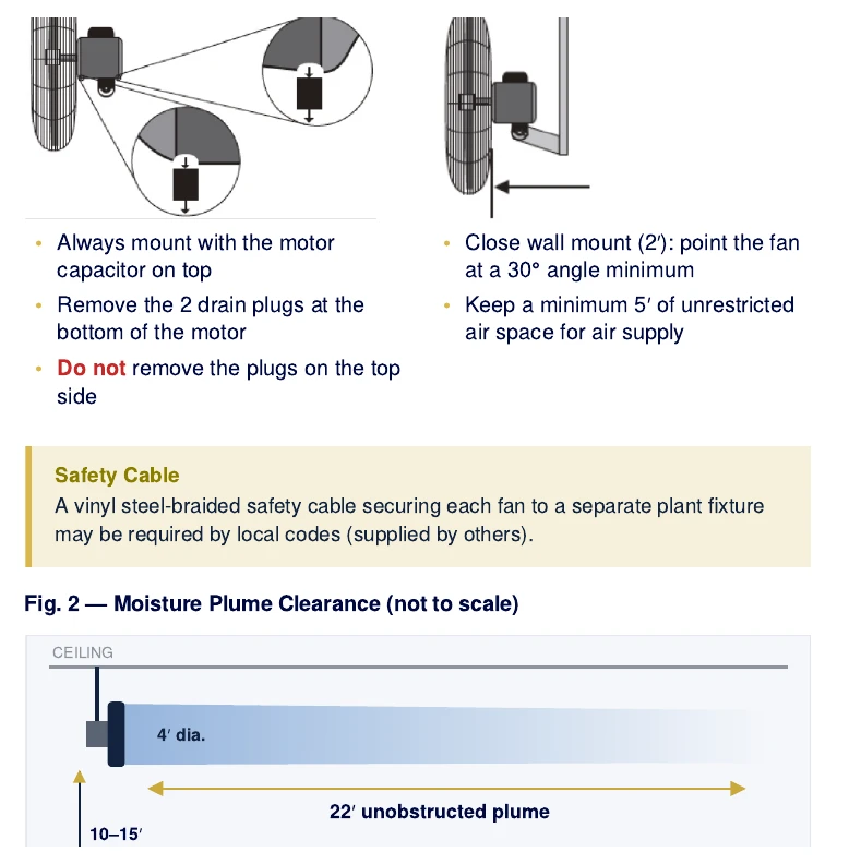
- Plan accessible mounting roughly 10–15 feet above the floor.
- Keep the 4-foot-diameter, 22-foot-long plume clear of obstacles; aisleways can provide suitable paths.
- Introduce humidity upstream into the plant’s natural airflow toward the exhaust.
- Allow unrestricted air supply behind the fan. For close wall mounting, the reference calls for at least a 30° angle and 5 feet of unrestricted air space.
- Mount the motor with the capacitor on top. Remove the two bottom motor drain plugs; retain the plugs on top.
- Have the installer check structural support and any local requirement for an independent safety cable.
Brackets and aiming
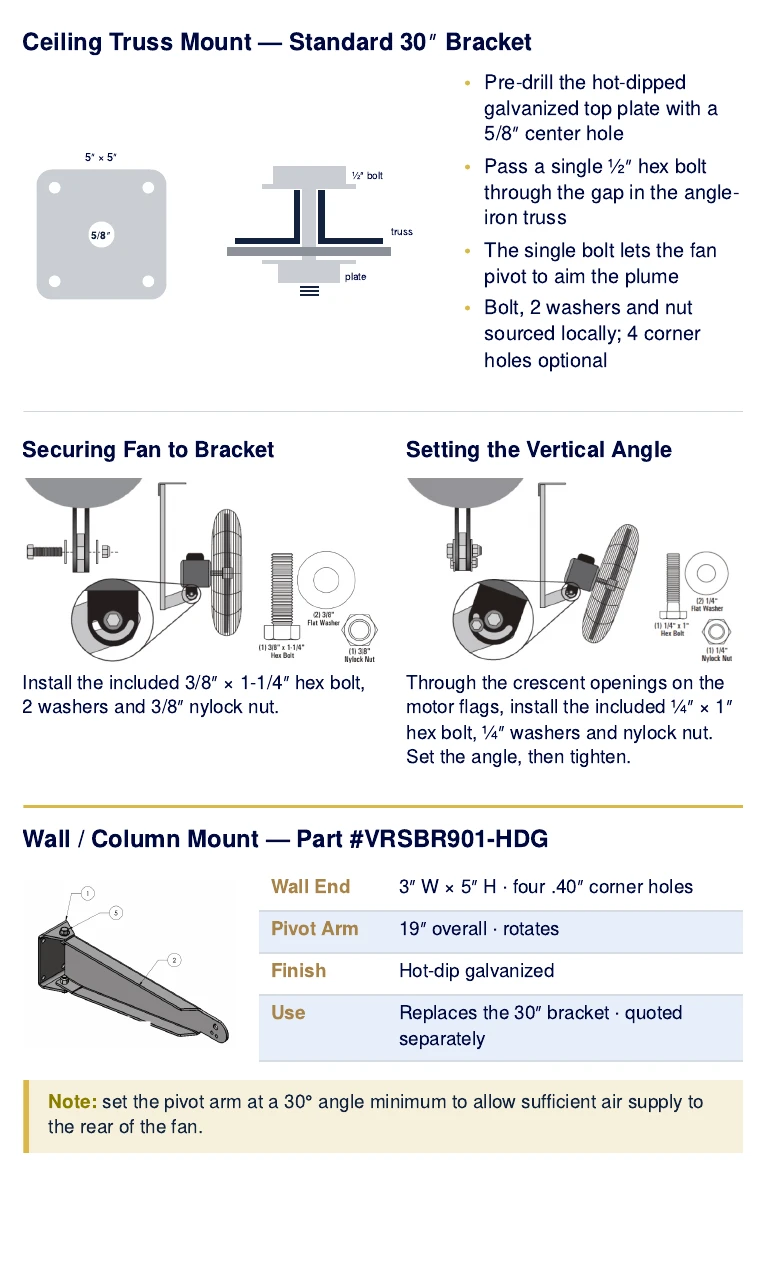
The standard 30-inch galvanized bracket has a 5-by-5-inch top plate. The reference shows a ⅝-inch center hole and a locally supplied ½-inch bolt with washers and nut through the truss gap. The center connection permits aiming.
The fan-to-bracket connection uses the supplied ⅜ × 1¼-inch bolt, washers and nylock nut. The motor’s crescent slots use the supplied ¼ × 1-inch hardware for vertical aiming. Tighten after positioning.
The optional VRSBR901-HDG wall/column bracket has a 19-inch pivot arm and a 3-by-5-inch wall plate with four 0.40-inch holes. Structural mounting and fastener suitability must be confirmed for the installation.
Mist ring and drop-down connection
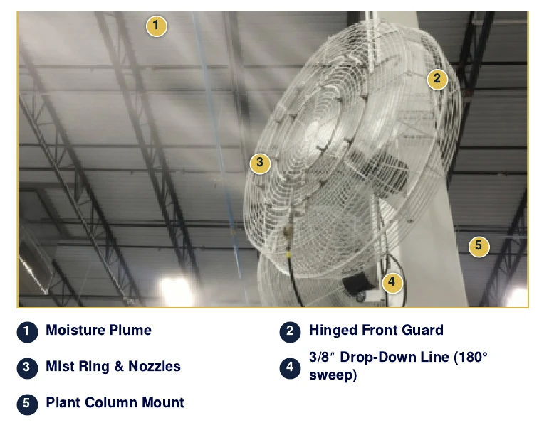
Center the ring on the front guard and secure it with four or five 4-inch zip ties. Feed it from the ceiling’s ⅜-inch supply through the ball-valve assembly.
Leave enough tube for a flexible 180° sweep into the valve without a side load. At the last fan, use a smooth 90° turn into the drop instead of an unnecessary tee.
Power & operating sequence
Separate fan power from the low-voltage control signal.
Fan power and relays
Fans use plant power. The pump station supplies a 24 VAC on/off signal to a remote relay or contactor, which switches that plant power. Use the motor nameplate and a qualified electrician to size and connect the circuit.
Provide a dedicated switch and a drip loop at each fan. The reference lists RIB2401B for one or two single-phase fans and RIB243P for up to eight three-phase fans, subject to actual load and relay ratings. Dry-contact and wireless relay arrangements are also described for appropriate installations.
Air before and after the mist
Use the exterior fan-override toggle for fan-only testing and rotation checks on stations wired for that function.
- Humidity demand starts the fans immediately through Q0.
- After the 10-second T1 delay, the pump starts. The pressure-proving timer checks for an HPS signal.
- At the set point, the pump stops and the EDV opens so the nozzle springs close.
- The fans run for the 10-second T2 delay, clearing residual mist, then stop.
Maintenance & troubleshooting
Inspect the fan safely and check the cause of poor airflow or wetting.
Fan symptoms and checks
- Isolate and depressurize before opening the hinged front guard for cleaning.
- Keep the mist ring centered and securely tied.
- Inspect brackets and hardware when servicing the fan.
Noise or vibration
- Possible cause
- Loose mounting or damaged blades.
- What to check
- Stop and isolate the fan; inspect hardware, blades, bracket and safety cable.
Incorrect rotation
- Possible cause
- Incorrect motor wiring.
- What to check
- Have a qualified electrician correct wiring according to the motor nameplate, then verify rotation with the guarded fan.
Fans do not run or override has no effect
- Possible cause
- No control signal, relay fault or wiring problem.
- What to check
- Check the fan-control connection and relay using the correct schematic.
Wet spots or excessive water use
- Possible cause
- Too much nozzle output, insufficient airflow or incorrect timing.
- What to check
- Check nozzle size, fan operation, plume clearance and fan/pump delays.
Humidity stays below set point
- Possible cause
- Insufficient output, blocked nozzles or poor placement.
- What to check
- Compare actual load with system output; check every nozzle and the distribution of airflow.
Parts & references
Continue with related guides, parts and the original PDF.
Related parts
- VBS2424" industrial basket fan — single phase
- VBS24-11024" industrial basket fan — with 110 V cord
- VBS243A24" industrial basket fan — three phase
- VBS36A36" industrial basket fan — single phase
- VBS36A-C11536" industrial basket fan — with 115 V cord
- VBS36A-C23036" industrial basket fan — with 230 V cord
- VBS36CF36" industrial basket fan — three phase
- VRSBR2-HDG24" hot-dip galvanized ceiling bracket
- VRSBR3-HDG30" hot-dip galvanized ceiling bracket
Original & related PDFs
This web guide is adapted from the IHC reference linked below. The original PDF retains its diagrams, document revision and printable layout.