Before service: Isolate power and water and verify zero pressure. Read the safety instructions →
Plan & prepare
Confirm the design, site conditions and installation responsibilities.
Before inspection or service
A complete installation, from pump to nozzle
The handbook follows the FanMist station, electrical controls, fans, distribution tubing, mist rings, drain and water supply through flushing and startup. Installation requires qualified mechanical, electrical and plumbing personnel and the approved site design.
Match equipment and utilities to the quote and nameplates. The system operates at approximately 1,000 psi; do not use generic low-pressure components in its high-pressure distribution.
Pre-installation checklist
- Confirm ordered pump capacity, fan locations, electrical supplies and delivery contents.
- Plan a climate-controlled pump location with accessible water, power, drainage and service space.
- Check the fan layout for clear evaporation paths and suitable structural mounting points.
- Provide lift access, tubing cutters, suitable fasteners, 14–24-inch ties for column routes and 4-inch ties for mist rings.
- Plan flushing equipment and coordinated operators before fitting the nozzles.
- Provide appropriate water treatment and inlet filtration before commissioning.
Pump station & fans
Position the equipment for safe access and an unobstructed plume.
Pump station placement and utilities
Locate the station in a climate-controlled, serviceable area on a stable, level support. The handbook recommends approximately 24–30 inches of clearance at the front and sides. Its approximate large-station envelope is 37 × 20 × 48 inches including the stand; check the actual enclosure drawing.
Provide the correct dedicated electrical branch, accessible water isolation and a planned EDV discharge route. Match the installed pump’s inlet-pressure limit and provide a continuous supply of at least 1.5 times station pump flow.
Fan location and evaporation space
The handbook uses a typical 10–15-foot mounting height and an approximately 4-foot-diameter by 22-foot-long unobstructed mist path. Confirm that racks, machinery, walls and stored materials will not intercept the plume.
Fan airflow must be adequate for the installed nozzle output. The handbook uses 80 CFM per lb/hr or higher; the component and sizing references state greater than 75. Use the specified design and actual fan/nozzle combination, not a nominal fan diameter alone.
Brackets, orientation and wiring
- Use the specified bracket and structurally suitable support. The illustrated ceiling bracket uses a ⅝-inch center hole with a ½-inch bolt and appropriate securing hardware.
- Keep the inlet and forward mist path clear; use the fan component guide’s model-specific placement requirements.
- For wall placement, the handbook illustrates angling the fan away from the wall rather than aiming along an obstructed surface.
- Provide a local fan disconnect, correct nameplate wiring and a drip loop. Test forward airflow before mist operation.
- Install the motor capacitor on top where fitted and remove the designated lower drain plugs.
Tubing, rings & valves
Build the high-pressure network and connect each fan’s isolation valve.
Nylon tube specifications and routes
The source specifies black Polyamide 12 tube, with a stated ±0.004-inch dimensional tolerance. Use tubing and fittings rated for the system and avoid sharp bends, kinks and abrasion.
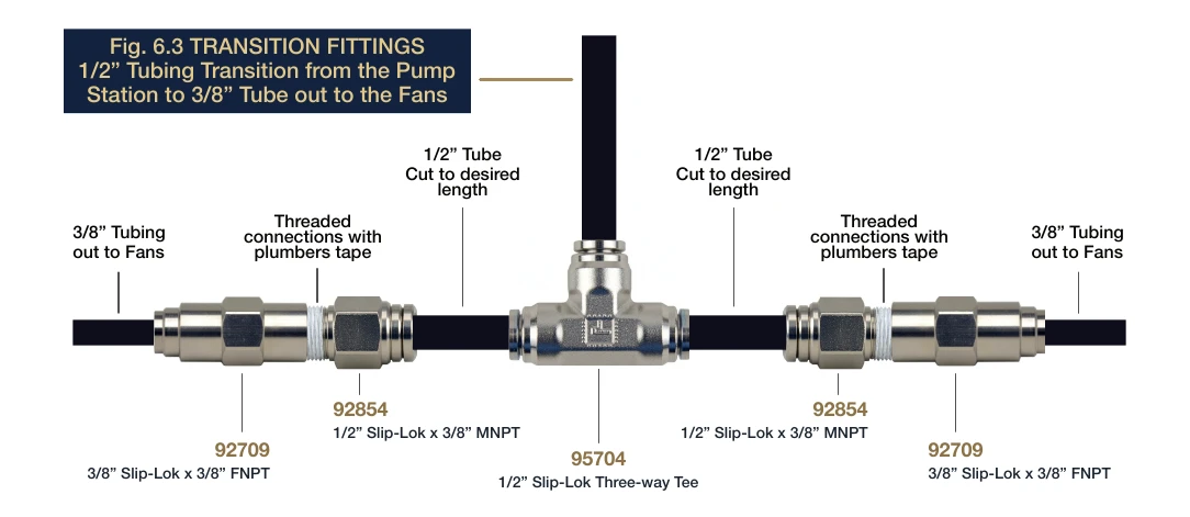
Use the approved main distribution route, then branch toward the fans. The illustrated transition uses 92854, ½-inch Slip-Lok × ⅜-inch MNPT, with 92709, ⅜-inch Slip-Lok × ⅜-inch FNPT. A 95704 tee splits the ½-inch main.
For ordering, 90063 is the 500-foot ⅜-inch roll and 93072 is the 100-foot roll in the current catalog. The handbook reverses these lengths; verify the current part listing.
| Tube | Outside diameter | Inside diameter | Wall |
|---|---|---|---|
| ½ inch | 0.500 inch | 0.375 inch | 0.062 inch |
| ⅜ inch | 0.375 inch | 0.275 inch | 0.050 inch |
Tube preparation and Slip-Lok connections
If an O-ring requires replacement, remove the collar and worn seal carefully, fit the correct new primary O-ring and reinstall the collar. The optional urethane backup ring separates the ferrule teeth from the primary seal. Confirm the size before reassembly.
- Uncoil the tube and let it relax. Work in manageable lengths and form smooth bends rather than forcing tight corners.
- Cut the end square with a tubing cutter. Lightly smooth the cut edge without scratching the sealing surface.
- Push the tube fully into the correct-size Slip-Lok fitting, then pull back to lock it.
- Support the route with suitable ties or clamps; the handbook illustrates roughly 10-foot support spacing for long runs.
- To remove a connection, isolate the supply and verify zero pressure, push the tube in, depress the release collar and withdraw the tube.
Drop-down line and mist ring
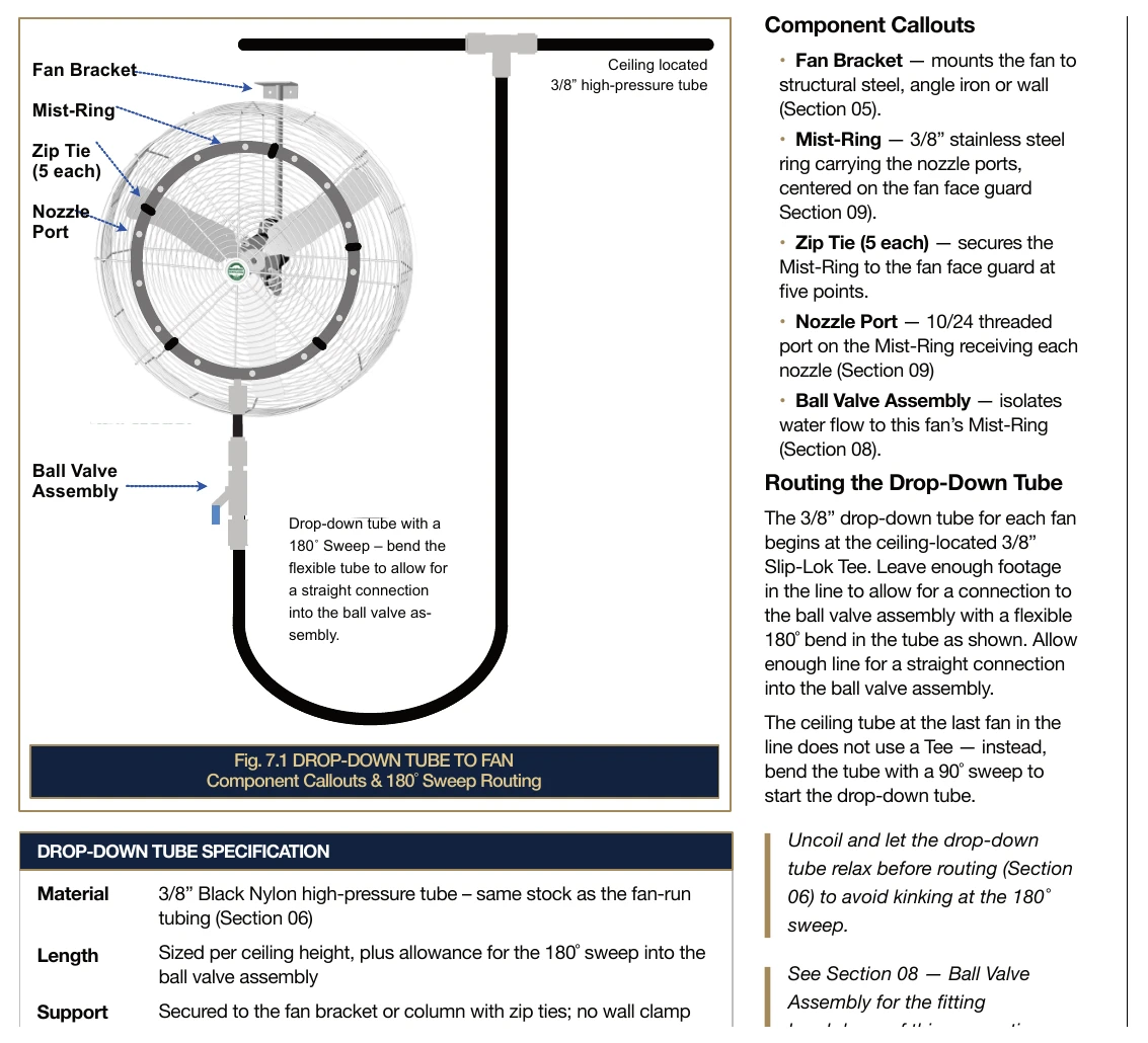
Run a ⅜-inch drop from the overhead line to each fan. A three-way tee starts an intermediate drop; at the last fan, the handbook uses a smooth 90° sweep rather than an unnecessary tee.
Leave enough flexible tube for the 180° return sweep beneath the ring’s ball valve. Secure the drop to the column or fixture, and center the mist ring on the guard using the specified ties.
Ball valve assembly
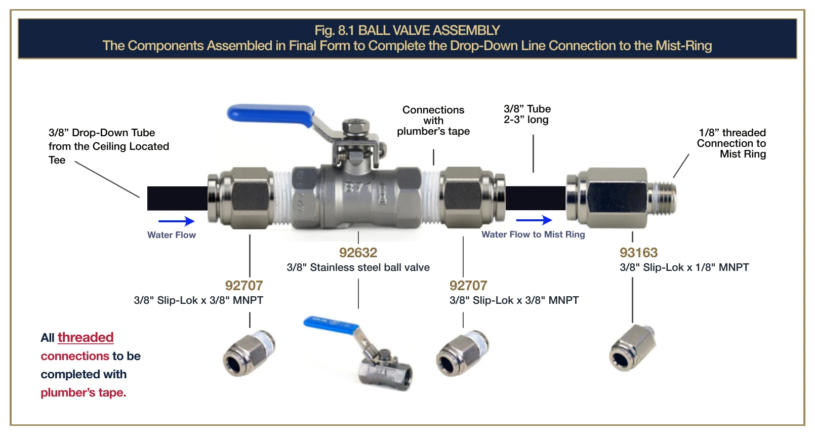
- Connect two 92707 adapters, ⅜-inch Slip-Lok × ⅜-inch MNPT, to ball valve 92632 using the specified thread-sealing tape.
- Connect 93163, ⅜-inch Slip-Lok × ⅛-inch MNPT, to the mist-ring inlet.
- Join the valve outlet adapter to the ring adapter with the short ⅜-inch tube shown in the assembly drawing.
- Insert the drop-down supply tube into the valve’s inlet fitting and pull back to lock.
- Leave each fan valve closed until that ring is ready for the flushing procedure.
Ring sizes and nozzle installation
Complete MR-series assemblies include the ring and ball-valve assembly; nozzles are selected separately. Install nozzles only after the lines and rings have been flushed. Keep each nozzle’s filter in place and tighten finger-tight.
Drain, controls & water
Complete the pressure-release path and the water and humidity controls.
EDV drain routing
On shutdown, the normally open EDV releases line pressure so the spring-loaded nozzles close. Route its drain tube at least 3 inches above the highest point of the high-pressure distribution before it descends to the approved destination.
The source illustrates discharge to a floor drain, a properly arranged bladder-tank reclaim system or an RO storage arrangement. Reclaim piping, isolation and check valves must match the approved plumbing design. A restricted or incorrectly routed drain can prevent prompt pressure release.
Humidistat and control connections
Mount the HRO20 at a representative, accessible location away from a fan plume, door draft or localized heat. Wire its terminals 1 / 2 / 8 to station NEUTRAL / HOT / RELAY using the specified three-wire 18 AWG cable.
Wire FAN CONTROL to the correct fan-relay coil using two-wire 18 AWG cable. Fan motors receive separate plant power through the relay contacts. Verify the actual controller’s switching differential rather than relying on conflicting dead-band values in older references.
Supply, pre-filter and treatment
Provide a stable supply with enough flow for the station, plus the correct 5-micron pre-filter. The reference calls for a filter change every 500 hours or annually at minimum. Housing 92609 uses cartridge 92608 and wrench 95062.
Resolve hardness and dissolved-mineral requirements before startup. Softening and scale control do not remove dissolved solids in the same way as RO. Sensitive products and clean processes can require more treatment than protection against pump scale alone.
Flush & commission
Remove construction debris before installing nozzles and verify a complete operating cycle.
Flush every line and ring
Prepare two 94506 flushing extensions, clear drain tubes sized as specified in the handbook, secure collection buckets and lift access. The reference calls for three coordinated roles: pump-station control, fan/lift work and bucket handling.
Begin at the fan nearest the pump and proceed outward. Keep nozzles off during flushing, keep the fan locally off and start with that ring’s ball valve closed.
- With the pump isolated and pressure verified at zero, plug all but the two top ports of the ring.
- Fit the two flushing extensions and secured drain tubes to the open top ports. Route the tubes into the collection buckets.
- Open that ring’s ball valve. When all operators are ready and clear, signal the pump operator to start the flushing run; allow for the fan/pump start delay.
- The handbook calls for approximately 1.5–3 gallons per ring. Watch the discharge and bucket level throughout.
- Stop the pump, isolate it and verify zero pressure before touching the connections. Close the ring’s ball valve.
- Remove the flushing equipment and temporary plugs; install the selected nozzles finger-tight, keeping their filters fitted.
- Return that fan’s local switch to on and continue to the next ring. Complete all rings before normal startup.
Final startup checklist
Normal pressure proving uses the station’s configured timing. The handbook distinguishes an initial-start setting from the normal 25-second interval; any temporary commissioning change should be made and restored by the responsible technician.
- Confirm mechanical installation, water treatment, filtration, all electrical connections, drain routing, flushing and nozzle installation are complete.
- Check supply availability, open the appropriate fan ball valves and verify fan rotation with override.
- With covers and guards in place, restore the water supply and set a test humidity call.
- Confirm fans start first, the pump follows approximately 10 seconds later, and system pressure reaches approximately 1,000 psi.
- Observe for leaks, abnormal noise, vibration or pressure fluctuations; stop and correct any problem.
- End the humidity call. Confirm pump stop, EDV depressurization and a further 10 seconds of fan airflow.
- Return the humidistat to the design set point and record the commissioning results.
Parts & references
Continue with related guides, parts and the original PDF.
Original & related PDFs
This web guide is adapted from the IHC reference linked below. The original PDF retains its diagrams, document revision and printable layout.