Before service: Isolate power and water and verify zero pressure. Read the safety instructions →
Identification & specifications
Identify the normally open valve and its matching coil.
Before inspection or service
What the drain valve does
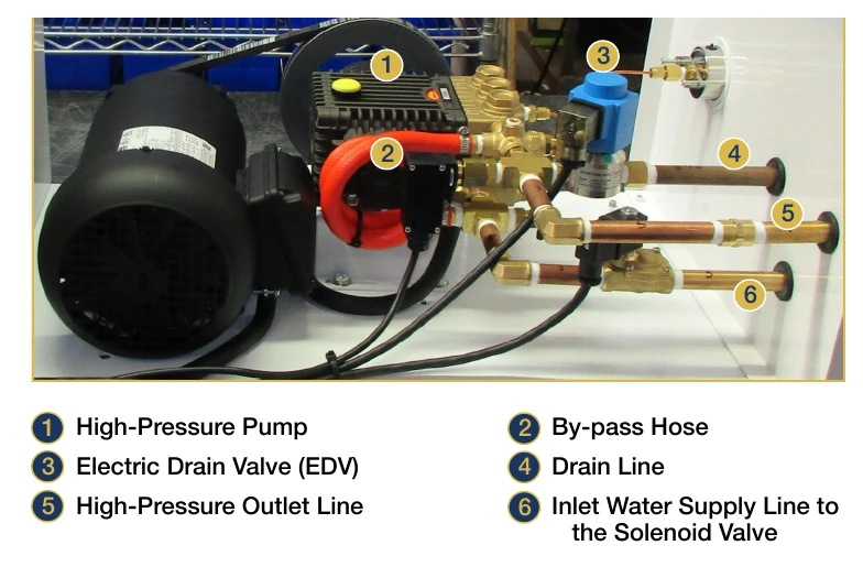
The Danfoss EV220BSS electric drain valve (EDV), part 95001, is a normally open, two-port solenoid valve on the pump’s high-pressure discharge manifold. Energizing its coil closes the drain so the system can build pressure. Removing power opens the drain, including during a power failure.
At shutdown, pressure falls below the nozzles’ approximately 300 psi closing threshold. The nozzle springs close and the fans continue briefly to clear the remaining mist. The reference describes approximately ¼ gallon draining per cycle.
Valve specifications and part family
| Item | Specification / part |
|---|---|
| Valve | 95001 · Danfoss EV220BSS · 2/2-way · normally open |
| Body / ports | Stainless steel · ¼-inch FNPT |
| Seals / diaphragm | NBR/FKM (nitrile/Viton) seals; elastomer diaphragm |
| FanMist maximum pressure | 1,000 psi |
| Coils | 95003: 24 V · 95004: 110 V · 95005: 220 V |
| Connector | 95002.DIN · four-spade DIN plug; IP65 with connector fitted |
| Approximate size / weight | 140–160 mm overall height · 0.6–0.8 kg |
Installation & operation
Locate the valve, route its drain and understand the operating cycle.
Manifold location and drain routing
Mount on the high-pressure manifold downstream of the pump discharge. Leave room to remove the coil and connector. The reference permits vertical or horizontal mounting.
Connect the outlet to a dedicated ⅜-inch drain line. Route it at least 3 inches above the highest point of the high-pressure tubing before running to the approved drain or recovery tank. This limits unnecessary draining of the distribution lines.
Valve state through a complete cycle
| Stage | EDV and system response |
|---|---|
| Idle / fan lead | Coil off; valve open. Fans start before water is atomized. |
| Pump starts | PLC energizes the coil and closes the drain as the pump starts. |
| Normal run | Valve remains closed; system operates at approximately 1,000 psi. |
| Humidity demand ends | Pump stops and coil de-energizes; valve opens immediately. |
| Depressurization | Pressure drops below 300 psi; nozzle springs close. Fans run for 10 more seconds. |
| Power loss | Coil loses power and the normally open valve releases pressure. |
Maintenance & replacement
Check the drain function, connector, coil and seals.
Maintenance schedule
| Interval | Work |
|---|---|
| Every 500 hours | Inspect for leaks, corrosion and damage; verify opening on pump shutdown. |
| Annually | Inspect electrical connections and coil resistance; clear drain-line restrictions. |
| Every two years | The EDV reference calls for preventive seal and diaphragm replacement where accessible. |
| As needed | Isolate and depressurize before cleaning debris from the valve seat and orifices. |
Inspection and functional test
- Observe a normal shutdown with the equipment assembled and guarded. Confirm that pressure falls promptly and nozzles stop without dripping.
- Before touching wiring or removing parts, isolate power and water and verify zero pressure.
- Inspect the body, drain line, DIN connector and wiring. Check for loose connections, moisture, corrosion or a restricted drain.
- A qualified technician can check coil resistance against the correct coil specification. Replace cracked, discolored or overheated coils with the matching voltage.
- If cleaning is required, remove the isolated valve, flush its body and orifices with clean water and replace worn seals before reassembly.
When to replace the complete valve
- Heavy internal wear or corrosion.
- Failure to operate after cleaning and coil replacement.
- Visible body damage.
- Leakage that persists after seal replacement.
Troubleshooting
Use the symptom to separate a drain restriction from an electrical or valve fault.
EDV symptoms and checks
Valve does not open on shutdown
- Possible cause
- Coil remains energized, or a faulty coil or mechanism prevents operation.
- What to check
- Have a qualified technician verify the PLC output and wiring, test the coil and inspect the isolated valve.
Valve leaks while closed
- Possible cause
- Worn seals or diaphragm, or debris in the seat.
- What to check
- Isolate and depressurize; clean internals and replace damaged seals, diaphragm or valve.
Slow or incomplete depressurization
- Possible cause
- Restricted drain line or valve orifice.
- What to check
- Inspect and clear the isolated drain path.
Coil overheats or smells burned
- Possible cause
- Wrong supply voltage or an unsuitable duty rating.
- What to check
- Stop operation and verify coil voltage and continuous-duty suitability.
Pressure will not build
- Possible cause
- EDV remains open because its coil is not energized or the valve is stuck.
- What to check
- Check the PLC output, coil and isolated valve for debris or binding.
Valve chatters or vibrates
- Possible cause
- Low or unstable coil supply voltage.
- What to check
- Have a qualified technician check the supply and connections.
Nozzles drip after shutdown
- Possible cause
- EDV does not open fully, or its drain line is restricted.
- What to check
- Observe shutdown pressure, then isolate the system and inspect the valve and drain line.
Parts & references
Continue with related guides, parts and the original PDF.
Related parts
Original & related PDFs
This web guide is adapted from the IHC reference linked below. The original PDF retains its diagrams, document revision and printable layout.