Before service: Isolate power and water and verify zero pressure. Read the safety instructions →
Identification & supply
Identify the inlet valve and the water supply it controls.
Before inspection or service
The pump’s incoming-water valve
The inlet solenoid is a normally closed, ⅜-inch brass valve after the 5-micron pre-filter and before the high-pressure pump. It opens when PLC Output 1 commands the pump to run, then closes when the pump stops. The main supply valve normally remains on during service operation.
This is a low-pressure inlet component. It is different from the normally open electric drain valve on the high-pressure side.
Parts and supply requirements
| Item | Reference specification |
|---|---|
| 93368 | Inlet valve with 115 V coil for a matching pump station |
| 93596 | Inlet valve with 230 V coil for a matching pump station |
| Valve | Two-way, normally closed · ⅜-inch brass body |
| Control | PLC Output 1 · DIN plug with four-spade connector |
| Station supply | 25–100 psi in this station reference; confirm the installed pump’s own inlet-pressure limit |
| Available flow | Continuous, uninterrupted supply of at least 1.5 times the station’s rated pump capacity |
| Water path | Water treatment → 5-micron pre-filter 92608 → inlet solenoid → pump |
Identify the components
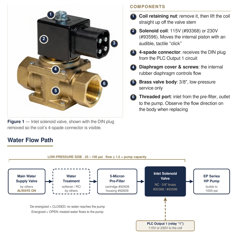
- The retaining nut holds the coil on the stem.
- The coil moves the internal piston; normal operation produces an audible or tactile click.
- The diaphragm controls flow. Observe the body’s flow-direction marking when replacing the valve.
- The source recommends keeping a spare matched coil and DIN plug.
Sequence & electrical integration
Understand how the inlet valve follows the pump command.
Operating sequence
| Stage | Valve state |
|---|---|
| No humidity demand | De-energized and closed; pump off. |
| Fan lead, first 10 seconds | Fans run; valve remains closed. |
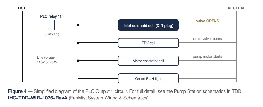
| Pump starts | Output 1 energizes the coil, EDV circuit, motor contactor and green RUN light; inlet valve opens. |
| Pressure proving | PLC waits for the HPS signal during its 25-second pressure timer. |
| Demand ends | Pump stops and inlet coil de-energizes immediately; valve closes. |
| Fan run-on | Fans run 10 more seconds; valve stays closed. |
Coil voltage and shared output
The inlet coil shares Output 1 with the EDV coil, motor-start contactor and green RUN indicator. The coil voltage must match the station supply and installed wiring. Do not assume every station uses the same coil.
Electrical measurements on an energized station are for qualified personnel. No voltage during a pump command points toward the wiring or PLC output; correct voltage with no movement points toward the coil or valve.
Inspection & replacement
Check the connector, coil and diaphragm before selecting replacement parts.
Inspection procedure
- Stop and isolate the system, shut off the water supply, and verify zero pressure.
- Inspect the DIN connector for loose terminals, damage, moisture or corrosion. Clean carbon from the connector contacts and replace a damaged plug.
- Remove the retaining nut and lift the isolated coil straight off the stem. Bulging, burns, melted plastic or water intrusion are reasons to replace it with the correct voltage model.
- If water passes when the valve is off, or flow remains restricted when it is on, inspect for scale or a damaged diaphragm. The IHC guide recommends complete valve-body replacement rather than diaphragm repair.
- Reassemble, secure all connections and guards, restore water, then perform a controlled operating cycle. Confirm opening only on a pump command, pressure recovery and closing at shutdown.
Symptoms and checks
Clicking but no water flow
- Possible cause
- Debris, scale or a damaged diaphragm.
- What to check
- Inspect the isolated valve; replace the complete body and check water treatment.
No click when commanded to run
- Possible cause
- Failed coil, bad DIN connection or missing PLC output.
- What to check
- Check connector condition and correct coil voltage; have a qualified technician test Output 1.
Intermittent flow or erratic pump pressure
- Possible cause
- Loose DIN plug, unstable voltage or a failing coil.
- What to check
- Inspect and secure connections with power isolated; check voltage and coil condition.
Low inlet pressure or cavitation
- Possible cause
- Blocked filter, restricted supply or a scaled valve.
- What to check
- Replace filter 92608 as needed, check treatment and supply flow, and clean or replace the valve.
Water flows after the pump stops
- Possible cause
- Valve stuck open or torn diaphragm.
- What to check
- Replace the complete valve body.
Slow pressure build or red FAULT light
- Possible cause
- Insufficient water through the inlet path or a leak.
- What to check
- Check the inlet gauge, filter, valve and distribution lines before resetting the fault.
Parts & references
Continue with related guides, parts and the original PDF.
Related parts
Original & related PDFs
This web guide is adapted from the IHC reference linked below. The original PDF retains its diagrams, document revision and printable layout.