All Posts By

Ray Reiff

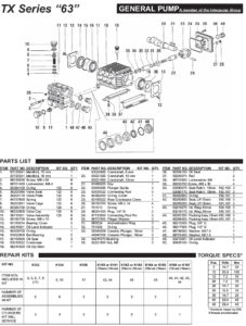
TX Series 63 General Pump Specifications, Parts, Repair Kits and Servicing

By | Pump Maintenance and Trouble Shooting

All FanMist Systems use the General Pump TX Series 63 Pumps.  Included in this post are the most important pdf documents for specifications, parts, repair kits, servicing and trouble shooting.  Select the button below to download the pdf’s.

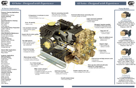
The image below shows a cross section of why General Pump is a leading manufacturer of high quality high pressure pumps used in the humidification industry.

TX Series 63 Pump Specifications, Parts and Repair Kits


General Pump Specs–Parts–Repair Kits pdf General Pump Servicing Instructions pdf

A Discussion on High Pressure Interpump (General Pump in US) Vs Cat Pump

By | High Pressure Pump Operation

The following is a discussion by our factory manufacturer of all of our pump stations regarding the use of our standard high pressure “General Pump” in all of our high pressure systems since 1989.

All the high pressure pumps we use are triplex plunger pumps.  These include Interpump (Called General Pump in the US) and CAT.  Both of these are reasonably similar in terms of design and performance.

We use mostly General simply due to the fact that we have been using their pumps since day 1 (1989) and have always experienced good reliable performance.  We also use CAT although mostly due to customer requests.

CAT does have a solid reputation which is at least partially a result of years past when their units were considered more of an industrial design.  Over the years, however, other manufacturers have improved their products such that today, there is little actual performance advantage between the different options.

Our experience has not shown that the CAT pumps can run longer or need less maintenance.  The main issue for causing pump maintenance is the pump seals and how long they last before they need to be replaced.  Our experience indicates that there is little difference.  The biggest factor in terms of seal life is the actual water condition and operating parameters of the pump itself.  Both of these manufacturers have similar design (they would appear identical to the average user) although there are some specific differences that each proposes makes their units unique.  Because we see little difference in terms of performance but a huge difference in terms of cost, we primarily use the General pump option unless a customer makes a specific request.  It is hard to convince some customers of the advantage of CAT based on the cost difference.

Accessing the Humidification High Pressure Pump and Changing the Oil

By | Pump Maintenance and Trouble Shooting

Accessing the Pump to Change the Oil

You will need to remove the Enclosure Cover which is connected with 8 phillips head screws.  Remove the screws and slightly pull the cover away from the housing on both sides to release from the insulation.  Slide the cover off the housing.

Changing the Oil

Run the pump for a few minutes to heart up the oil so it will flow easier..  Remove the nut on the end of the oil drain hose attached to the side of the bare pump.  Drain the oil.  Put the nut back on the drain hose.  Add oil through the yellow ventilated cap on the top of the bare pump.  Add until about ½ way on the sight glass.


Components and Their Functions of a Humidification High Pressure Pump Station

By | High Pressure Pump Operation

NEPTRONIC CONTROLLER HUMIDISTAT: We include a 24 VAC transformer in the pump.  The Neptronic is only closing one relay, a three conductor wire ID used. 

DANFOSS VALVES: Are of two types.  Electric Drain Valves and 3/2 Solenoid Valves include zone and drain in on – all stainless steel.  We typically plumb and wire the zone valves within the pump enclosure OR on the bottom shelf of our table top if there are too many valves to include in a pump enclosure.  These valves can be located remotely but that will require that the necessary voltage be brought from the pump to the valve.  In these cases, as long as we know that is the intent, we would provide the contact points in the pump enclosure to land the valve wiring.  The valve control would still be integrated into the pump design. 

EDV: This is an electric drain valve.  It is typically use for single zone pumps to release the pressure (and drain the line) whenever the pump is turned off.  If the system includes multiple zones, we use the DANFOSS 3/2 valve  This is a zone valve and drain valve in one which allows an individual zone to be drained without affecting the other zones in the system. 

PLC: Our plc does provide for sequential switching of multiple relays with a programmable time that can be adjusted on site.  The program can be written to achieve almost any function required.  Currently, the program provides for the fan to turn on first, then the appropriate zone valve, then the inlet solenoid valve, then the motor.  It sequentially turns off these components in the reverse order. 

PRESSURE FAULT INDICATOR LIGHT: The plc controls the operation of the pump.  As part of that, we include a low pressure OR high pressure switch in the pump plumbing.  The signal from this switch is one of the inputs for the plc.  The plc will allow the pump to run for a programmable period of time waiting for the return signal from the switch.  If it is not received in the preset time, the plc will sequentially turn off the components and illuminate a red indicator light that we include on the pump housing.  The plc must be reset to re-initiate the operation of the pump thereby requiring a specific action (fix the problem) before the pump can run again.  The plc will also track the number of pressure faults that occur mostly for trouble shooting purposes.  This function is ongoing and will shut the pump off any time during the operation of the return signal from the switch is lost for the programmed period of time. 

500 HOUR INDICATOR LIGHT: The plc tracks operating time.  Once 500 hours is achieved, the plc sends a signal to an amber indicator light that we include on the pump housing.  It will also display a ‘Maintenance Required’ message on the plc’s LCD display.  This light will stay illuminated until the operating counter is reset.  It will then start again counting until the next 500 hours are achieved.  This is an ongoing function. 

TRACKING OF PUMP FUNCTIONS: The plc will also keep track of the number of On/Off cycles (also for troubleshooting purposes) as well as the total number of hours of operating time.  Both of these counters/timers are resettable.

INDICATOR LIGHTS: These are panel mount LCD lights.  Green is illuminated whenever the pump is running; Red is illuminated whenever there is a pressure fault; Amber is illuminated once 500 hours is achieved. 

THERMAL PROTECTION: There are two forms of thermal protection that we provide.  A Thermal Relief Valve will open if the water supply to the pump exceeds 145 degrees.  This is usually a result of extreme bypass within the pump (in excess of 75% for an extended period fo time).  The valve opens and dumps enough water to cool down the inlet supply, usually about 8 ounces.  It will then close and wait until the water temperature again exceeds 145 degrees.  We also provide electric thermal protection for the entire pump with the inclusion of an appropriately sized circuit breaker (resetable) and for individual branch circuits with slow burn glass fuses (replaceable). 

SHORT CIRCUIT PROTECTION: See THERMAL PROTECTION above.  These components serve both purposes. 

INLET WATER SOLENOID VALVE: This is an electric valve that is provided on the inlet side of the pump.  It is energized (opened) by the PLC whenever necessary.  This valve prevents the need to turn the water supply on and off each time the pump is used. 

THERMAL RELIEF VALVE: See THERMAL PROTECTION above.

UNLOADER VALVE: This is a pressure regulator and bypass valve in one that is plumbed on the outlet side of the pump and allows the pressure output for the pump to be controlled (typically at 1000 psi) AND it allows any excess water from the output to be re-routed back to the pump inlet or to a holding tank depending on the system design. 

PUMP HOUR RUN METER: This is a simple panel mount analog hour meter that is provided on the pump enclosure.  It was more necessary before we included the plc in the pump build.  It currently serves as a redundant timer for the pumps operation.  It is visible from the outside of the pump whereas the plc timer is not.  

PRESSURE GAUGE: This is a glycerin filled panel mount gauge that is provided on the plumbing panel of the pump enclosure.  It is used to confirm the pressure output for the pump.  

HI/LOW PRESSURE SWITCH : We have two options.  The low water safety switch (LWSS) is plumbed on the inlet to the pump after the inlet solenoid valve.  It closes with incoming pressure of 15 psi (sending the return signal to the plc) and opens if the incoming pressure drops below 10 psi (terminating the return signal to the plc).  The High Pressure Switch (HPS) works the same way except it is plumbed on the high pressure side of the pump.  It comes in a variety of pressure settings.  The one we use is preset at 540 psi.  The advantage of the HPS is that is will shut the system down if the water supply is terminated (as the LWSS does) but it will also shut down the system if there is a breech in the high pressure line resulting in the pressure dropping from 1000 psi to below 540 psi. 

FAULT WARNINGS: See input above.

OTHER FUNCTIONS OFFERED

VARIABLE FREQUENCY DRIVE (VFD): We also provide variable frequency drive (VFD) units in pumps that require controlling of the pumps output volume, typically for multi zone systems.  The VFD will monitor the pressure output of the pump through a pressure transducer and speed up or slow down the motor to maintain the preset psi (typically 1000 psi) as flow through the system changes (opening or closing different zone valves).  This design allows, for example, a 3 gpm pump to safely operate as low as .15 gpm without bypass by simply slowing the motor down from 1750 rpm to 87.5 rpm.  In addition, because of the way it works, the VFD will typically consume as little as 50% of the normal current thereby saving a substantial amount of money in terms of operating costs.  Some customers include a VFD even in a single zone system to take advantage of this reduced operating cost.  

PUMP SIZING:  It is best if a pumps flow capacity is no more than twice the required systems flow.  So, 1 gpm is good for .5 gpm to 1 gpm, a 2 gpm is good for 1 gpm to 2 gpm, etc.  These numbers can be pushed a little bit but at 75% bypass, heat will build up triggering the thermal relief valve to dump the heated water.  If divided into zones, the smallest zone should be 50% (30% to 40% would be the extreme) of the total pumps capacity to prevent heat build up in the water supply (which would adversely affect the pump seals and lead to premature wear).  Obviously, there are exceptions and this is less of a factor if the operating time is relatively low (less than 5 minutes per cycle) because that short of time does not typically allow the water temperature to increase to a high enough level to be a concern.  The pump sizing is almost a non factor if a VFD is included in the pump design.    

FURTHER CLARIFICATIONS

480V refers specifically to a 480V 3 Phase unit which requires the inclusion of at least one transformer and several other changes to included components.

24V created simply refers to the need to include a 24VAC transformer in the pump to supply 24VAC to a controller or other device. 

What Can Cause a Humidification High Pressure Pump to Run Rough?

By | Pump Maintenance and Trouble Shooting

Trouble Shooting Cause of the High Pressure Pump Running Rough.

Begin by knowing the pump serial number and manufacture date which are both located on the metal tag attached to the the panel on the side of the enclosure.

Several types of causes can be kept in mind which cause a pump to run ‘rough’.  Try to identify how best to understand what rough means?  Is it loud?  Does the pressure fluctuate or jump while it is running?  Does the noise vary depending on the pumps output pressure?  Are the two pulleys properly aligned?  Is the pump leaking water below the brass head?  How many hours on the pump?  Has the oil ever been changed?

The most likely cause for a ‘rough’ running pump is debris in one of the 6 valves in the pump head.  If the pump is recently installed, small debris from installation such as teflon tape or brass shavings can be the cause.  These valves control the water flow inside the pump head as the pistons move back and forth.  If debris gets caught up in one of the valves, it can cause the pump to run rough.

The valves can be accessed by removing the 6 large bolts (three on top and three on the side) of the brass head.  They should be removed and inspected making sure there is nothing interfering with the function of the valve spring assembly.  This will require a 27mm socket and it is suggested to use a long “breaker bar” to provide additional leverage.  The bolts will be tight.

Once the bolts are removed, use a pair of needle nose pliers to remove the individual valves and the o-ring at the bottom of the port (one valve and one or-ring in each port).  Check the spring assembly to ensure nothing is broken (plastic housing or spring assembly).  If it is, it will need to be replaced.  If not, check for obvious debris that may be preventing the assembly from completely opening or completely closing.  Use compressed air to blow out the valve.  In some cases, the debris may not be noticeable.  Compressed air will assure the valve assembly is cleared.

While the bolts are removed, use compressed air to blow out all of the ports.  They are all interconnected so air into any given port will circulate through the other ports.  In some cases, the debris may have worked its way out of the valve but is still inside the port.  Blowing out the all of the ports will help ensure nothing is left inside.

Put the o-ring and the valve back into each port, thread the bolt back in place and turn the pump on to check the results of the cleaning.

There are occasions where we have to do this several times on our bench at the factory even though there is no visible debris.  It usually is corrected with the first cleaning but may take two or three times to get the debris out.

Other possibilities are low water supply causing cavitation within the pump head or broken or damaged crankcase inside the bare pump.  A detailed explanation of the pumps functional irregularity might help narrow it down.  A video is always helpful.  Images are good but not as useful as a video.


How to Check & Clean Danfoss Stainless Steel High Pressure Humidification Zone 3/2 Way Solenoid Valves

By | Pump Maintenance and Trouble Shooting

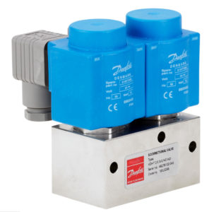
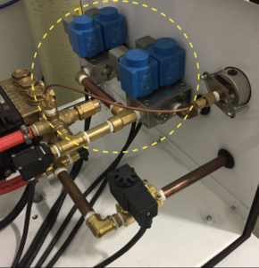
Shown are Danfoss Zone Valves
Used in High Pressure Humidification Pumps
for Multiple Zone Applications

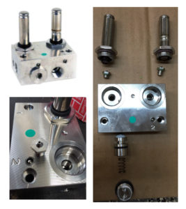
Danfoss 3/2 zone valves include a drain valve.  In the event of malfunction due to debris, the valve can be taken apart and cleaned.

Rinse it as thoroughly as possible, and purge with air if available.  After being cleaned of potential debris, it should be free to open/close 100%.

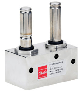
Images showing the 3/2 valve disassembled to demonstrate the several orifices that should be cleaned.

Danfoss 3/2 Zone Valve for High Pressure Multiple Zone Humidification Pumps

Danfoss 3/2 Zone Valve for High Pressure Multiple Zone Humidification Pumps


Danfoss (Uncapped) 3/2 Zone Valve for High Pressure Multiple Zone Humidification Pumps

Danfoss (Uncapped) 3/2 Zone Valve for High Pressure Multiple Zone Humidification Pumps


Danfoss (Disassembled) 3/2 Zone Valve for High Pressure Multiple Zone Humidification Pumps

Danfoss (Installed) 3/2 Zone Valve for High Pressure Multiple Zone Humidification Pumps


Danfoss (Disassembled) 3/2 Zone Valve for High Pressure Multiple Zone Humidification Pumps

Danfoss (Disassembled) 3/2 Zone Valve for High Pressure Multiple Zone Humidification Pumps

How to Check the Unloader Valve (Pressure Regulator)

By | Pump Maintenance and Trouble Shooting

How to Check the Unloader Valve (Pressure Regulator)
Installed in a “Tri-Plex Plunger Type”
General High Pressure Humidification Pump

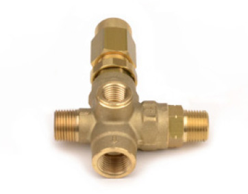
High Pressure General Pump Unloader Valve (Pressure Regulator)

High Pressure General Pump Unloader Valve (Pressure Regulator)


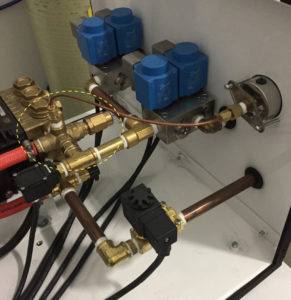
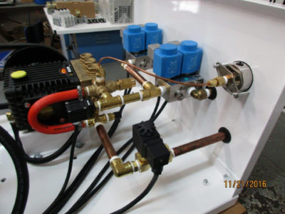
Unloader Valve Installed in High Pressure Pump Station

Unloader Valve Shown Installed in High Pressure Pump Station

This is a pressure regulator and bypass valve as a combined function in one valve that is plumbed on the outlet side of the pump and allows the pressure output for the pump to be controlled (typically at 1000 psi) AND it allows any excess water from the output to be re-routed back to the pump inlet or to a holding tank depending on the system design.

The unloader valve has seals and excessive bypass through the unloader valve will cause seals to wear prematurely.  Seals should last many years.  Excessive bypass occurs because the pump strains on the output side struggling to maintain greater than 50% output for extended periods of time.  We always seek to design pump size such that no single zone is significantly under 50% output at any time.  The cure for this the inclusion in the pump design of VFD (variable frequency drive).

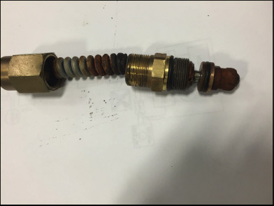
One sign of a defective regulator/unloader valve are pressure spikes.   The pressure may not be constant where a reading can be seen on the pressure gauge – but might be “spiking”.  To inspect the unloader, remove the acorn nut that has a hole in the end of it.   It is located on the output manifold of the pump.  The picture shows what a defective unloader/regulator valve looks like – it will have rust in it or on the spring – and will usually need to be replaced.    If no rust, you can spray WD 40 in it and loosen/tighten to ensure it is freed up.  The pressure should read 1000 psi while in operation.

Checking/Inspecting the Unloader/Regulator Valve if Malfunctioning:

  1. Turn the unit off.
  2. Locate the acorn nut that has a hole in the end of it – it is located on the output manifold of the pump.
  3. Mark how tight the acorn nut is currently threaded on.
  4. Un-thread the nut from the valve completely.
  5. Inspect the thick spring on the inside.
  6. If it is rusted or corroded, it needs to be replaced.
  7. If it is still clean (like shiny or polished steel), thread the nut back on however tight it was.
Defective Rusted Unloader/Regulator Valve

Defective Rusted Unloader/Regulator Valve

Instructions for the Replacement of the Unloader Valve

The process to remove the unloader valve involves a sequential removal and reassembly of all components and fittings from the 3/2 valves to the unloader valve.

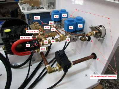
  1. Take several images of the plumbing before starting making special note of how far each fitting is threaded into its corresponding fitting to ensure everything is properly aligned when the reassembly is completed.
  2. Remove the fittings for the Outlet and Drain ports on the outer side of the housing
  3. Remove the blue coils from the two 3/2 valves noting which set of coils goes to zone 1 and zone 2.
  4. Unthread the two 3/2 valve blocks from the fittings that feed the valves
  5. Unthread the 90-degree elbow/nipple assembly from the brass street T fitting
  6. Unthread the brass street T fitting/nipple assembly from the brass T
  7. Remove the silver clip from the high-pressure switch and remove the switch from its brass base fitting
  8. Unthread the brass T from the unloader valve
  9. Remove the hose clamp from the bypass hose that is attached to the unloader valve
  10. Unthread the bypass hose fitting from the unloader valve
  11. Unthread the compression cap from the fitting that is attached to the top of the unloader valve
  12. Remove the small ferrule from inside the fitting noting the position it is in and set aside.  It will be used when reassembling the fitting.
  13. Push the copper tubing aside
  14. Unthread the base of the compression fitting from the unloader.
  15. Unthread the unloader from the pump.  The extension that is threaded into the end of the unloader valve (that the hexed cap is threaded onto) may have to be removed to provide enough clearance to unthread the unloader valve.
  16. Make sure each fitting has sufficient Teflon tape applied before threading into place.  6 to 8 revolutions of Teflon is recommended for each male thread.
  17. Thread the new unloader in place
  18. The extension on the end of the unloader may have to be removed to provide clearance to thread the unloader into the pump.
  19. Reassemble the plumbing in the reverse order in which it was removed making sure each fitting is threaded approximately the same depth as the original assembly.
Replacing Unloader Valve with Numbered Steps

Replacing Unloader Valve with Numbered Steps

Replacing Unloader Valve

Replacing Unloader Valve


How to Adjust the High Pressure Pump PLC to Re-Set “Timing Out”

By | High Pressure Pump Operation
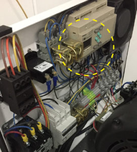
High Pressure Pump PLC

High Pressure Pump PLC


Adjusting the PLC
to increase the time for pump to pressurize before timing out: The PLC Screen shown inside yellow dotted area.  The time delay is pre-set at the factory for 25 seconds.

• Note: The steps below will basically double the amount of time (25 seconds to 65 seconds) of the factory setting.  The setting can be raised up to a maximum of 99 seconds if needed.

• Steps to adjust the delay timer for the high pressure switch signal. 

Power up the PLC.  

From the main screen:

1.  Press OK button, screen will change

2.  Use the down arrow to get to Parameter

3.  Press OK, screen will change

4.  ‘0’ will be changing from darkened to lightened.  Press OK

5.  ‘0’ will be blinking

6.  Press the down arrow until the ‘0’ changes to a ‘b’

7.  Press OK, ‘b’ will begin flashing with a darkened square.

8.  Press the Down arrow, the curser will drop down to the last ‘0’ on the ’25.00’ number at the bottom right hand side of the display.

9.  Press OK, the ‘0’ will begin blinking

10.  Press the left arrow 3 times to move the cursor to the ‘2’ of the ’25.00’ number.

11.  Press the up arrow to change the ‘2’ to a ‘6’

12.  Press OK

13.  Press ESC 2 times to return to the operational screen (timer now set for 65 seconds)

The High Pressure Pump and PLC Control Operation

By | High Pressure Pump Operation

All of our humidification systems function as a unified system, fully integrated and automated including a PLC controlled pump, zone humidistat/sensor and fans.  The pumps are prewired to the humidistat for testing during production and ship ready to install.

So, the system functions in the following manner: a humidistat/sensor (for each zone) sends a start signal to the pump whenever humidity is required (based on the settings in the humidistat).  Once the humidistat/sensor reaches the required humidity level, the start signal is terminated.

When the pump receives the start signal from the humidistat, the PLC sequentially turns on any fans that are part of the system; then the water supply to the pump, then the pump motor.  The delays between these functions can be programmed to factory set timing sequences consistent with each project as require.  Upon termination of the start signal, the PLC then sequentially stops the operation of the pump motor, then the valves, then the fans (if they are part of the system).  The time between this sequential shut down is also programmable and can be set based on the system or project requirements.

The PLC also handles the signal from the high pressure safety switch.  It will provide a delay (sufficient time to let the system fully charge).  This delay also allows for a loss of pressure for a short period of time (as when a second zone is opened while the system is already running thereby temporarily dropping the output pressure) without immediately terminating the system.  IF the pressure is lost beyond the set time (as when the water supply has been terminated OR there is a breech in the high pressure line resulting in a loss of high pressure in the system), the PLC will shut down the system and provide a signal to the red Pressure Fault indicator light included on the pump side panel.  The PLC requires a ‘reset’ to allow the system to begin operating again.

The plc also controls a green indicator light for when the pump is operating and a yellow indicator light which illuminates after a programmed period of time – typically 500 hours – providing a notice that it is time to change the oil, check for leaks from the pump seals, check the pulley belts for wear, check the filters for possible replacement, etc…

The PLC is the brains of our pump systems and can be programmed to do whatever is needed in terms of system functionality.  Although we do have a standard program, we can and do provide customized programs for clients that have specific operational requirements.

Currently, we also use the PLC to track things like the number of pressure faults, the number of on/off cycles, and the total run time of the pump.

Summary of Industrial Humidity Control Updates for Two Years

By | Updates

Sept 2017 – Thinking Water for Next Season Startup: We have recently partnered with Total Water Inc based in Madison WI to develop the 2nd generation “Blending System”  which greatly improves the practical functionality and cost associated with the ideal water treatment for all humidity control systems.  The water treatment system is called DIBS (Deionized Blending System).  This has now become our standard go to recommendation for all humidity control projects and worth your time to investigate its potential for your own use.  The strategic advantages: Lower capital cost verses RO; Low yearly maintenance; Non-corrosive / non aggressive water quality and No water wasted to drain.

2017-2018 Winter Mid season Guidelines: Check your pump hours: This has been a hard winter and you may be running more hours than you realize so a good time to for a visual inspection.  Review your user manual for frequency of pump hours to make your oil change.  Call us if you need resupply of oil.  Regarding water treatment, we will be shortly announcing our second generation design of the DI water blending system which greatly simplifies water treatment and is generally 1/3 of the cost of a comparable RO system.  Time to check your 5 micron water filter and check for any fouled nozzles or leaks.

April 2018 Post Season guidelines: Maintenance Prep for Shut-Down: The key to maintenance for this time of the season is the preparation procedures for shutting down humidity control equipment (review your equipment user manual) OR maintaining the equipment for periodic operation during off season such as running the equipment to maintain fresh water in the system (about every two weeks for 10-15 minutes).  Also, if you equipment requires oil changes or filter replacements, this is the right time of the year to plan for routine maintenance (as may be required).

Sept 2016 Pre-Season Water Treatment check: The proper water treatment for your type of system is the most critical component which affects short and long term maintenance frequencies.  Check with us to understand your options.  And most importantly, check to make sure your water treatment system is prepared with all routine maintenance requirements for your humidity control system startup.  Be aware of lead times for any parts replacement.  Generally parts require 1-2 weeks for ordering depending on whether parts are routinely needed as opposed to special order parts which can take longer.  Most humidity control systems are designed to maintain from 35-45% Relative Humidity.  The most universally accepted sweet spot for humidity control within most applications is 45% RH @ 72˚F.  Hygroscopic materials such as wood, paper and textiles naturally take on or give off moisture seeking “equalized moisture content” (EMC) to reach stability between the material and the realative humidity content in the air.  Electro-Static Discharge (ESD) is generally controlled at 35% RH and higher where static charges during process operations are generally avoided and potential issues for built in latent defects which cause end user malfunctions can otherwise be avoided during the production processes.  Be aware that Relative Humidity conditions above 50% can foster potential long term issues where moisture condensation on metal surfaces particularly in roof and wall areas over time can cause corrosion and degradation issues.

2016-2017 Mid Season: A tip for a simple procedure for cleaning nozzles – the nozzle unscrews and the spring and ball with the valve can be easily removed. Soak all pieces in warm vinegar and water solution OR soak in “Works” toilet bowl cleaner for 60 seconds, rinse and reassemble – you should have a new working nozzle with restored performance.  The latest development in high pressure is the use of fans to be able to accelerate moisture evaporation AND to allow the most amount of moisture to be evaporated in the least amount of airspace.  Fans are easily cost justified because of the greater control over the rate of evaporation along with flexibility of placement within your manufacturing spaces.  Moisture plumes are generally located where unobstructed air space allows for 4’ diameter by 20’ distribution of moisture for full evaporation.

2017 Post Season: The traditional season for adding humidity is generally October 15 through April 15.  Looking ahead for preparations of your equipment for following season startup should include the following:  Check Pump Oil and change per manual guidelines.  Change pump seals and valves as needed.  Check pulley belts.  Change water prefilters.  Flush water lines and replace with fresh water.