The pump stations designed by Industrial Humidity Control includes a thermal relieve valve which functions when water in the pump becomes overheated due to excessive bypass. In simple terms, excessive bypass occurs when not enough pressurized water can flow through the high pressure outlet and returns to the pump (the pump re-pressurizes water over and over). This normally occurs when the pump capacity exceeds twice the flow capacity to any single zone with a two zones not properly sized given the pump capacity. Pump stations with two zones require evenly matched zones so that any single zone is not substantially under 50% output of the total pump capacity. To avoid this, we normally will include a variable frequency drive (VFD) which permits any amount of water output regardless of the pump capacity and any number of zones per pump station. However, when excess bypass occurs, water temperature increases to dangerous levels whereby damage to components such as seals, pistons and O-rings can occur. The thermal relieve valve functions to avoid this occurrence by routing overly heated water to drain away.
Motors used in conjunction with high pressure pumps for humidity control systems can easily be incorporated into the pump design to meet project requirements specifying “Motors with Thermal Protection”.
According to section 7.2 of the WEG “Specifications of Electric Motors” referenced from www.weg.net:
Motors used for continuous duty must be protected against overloads by a device integrated to the motor, or an independent device, usually fitted with a thermal relay having rated or setting current equal to or below the value obtained by multiplying the rated motor power supply current ( In ) by the Service Factor ( SF ), as shown in table below:

WEG: Thermal Protection Chart for Electric Motors
The thermal protection is provided by means of thermoresistances ( calibrated resistances ), thermistors, thermostats or thermal protectors. The temperature detectors to be used are defined in accordance with the temperature class of the insulation materials used for each type of machine as well as based on customer requirements.
The following is a discussion by our factory manufacturer of all of our pump stations regarding the use of our standard high pressure “General Pump” in all of our high pressure systems since 1989.
All the high pressure pumps we use are triplex plunger pumps. These include Interpump (Called General Pump in the US) and CAT. Both of these are reasonably similar in terms of design and performance.
We use mostly General simply due to the fact that we have been using their pumps since day 1 (1989) and have always experienced good reliable performance. We also use CAT although mostly due to customer requests.
CAT does have a solid reputation which is at least partially a result of years past when their units were considered more of an industrial design. Over the years, however, other manufacturers have improved their products such that today, there is little actual performance advantage between the different options.
Our experience has not shown that the CAT pumps can run longer or need less maintenance. The main issue for causing pump maintenance is the pump seals and how long they last before they need to be replaced. Our experience indicates that there is little difference. The biggest factor in terms of seal life is the actual water condition and operating parameters of the pump itself. Both of these manufacturers have similar design (they would appear identical to the average user) although there are some specific differences that each proposes makes their units unique. Because we see little difference in terms of performance but a huge difference in terms of cost, we primarily use the General pump option unless a customer makes a specific request. It is hard to convince some customers of the advantage of CAT based on the cost difference.
NEPTRONIC CONTROLLER HUMIDISTAT: We include a 24 VAC transformer in the pump. The Neptronic is only closing one relay, a three conductor wire ID used.
DANFOSS VALVES: Are of two types. Electric Drain Valves and 3/2 Solenoid Valves include zone and drain in on – all stainless steel. We typically plumb and wire the zone valves within the pump enclosure OR on the bottom shelf of our table top if there are too many valves to include in a pump enclosure. These valves can be located remotely but that will require that the necessary voltage be brought from the pump to the valve. In these cases, as long as we know that is the intent, we would provide the contact points in the pump enclosure to land the valve wiring. The valve control would still be integrated into the pump design.
EDV: This is an electric drain valve. It is typically use for single zone pumps to release the pressure (and drain the line) whenever the pump is turned off. If the system includes multiple zones, we use the DANFOSS 3/2 valve This is a zone valve and drain valve in one which allows an individual zone to be drained without affecting the other zones in the system.
PLC: Our plc does provide for sequential switching of multiple relays with a programmable time that can be adjusted on site. The program can be written to achieve almost any function required. Currently, the program provides for the fan to turn on first, then the appropriate zone valve, then the inlet solenoid valve, then the motor. It sequentially turns off these components in the reverse order.
PRESSURE FAULT INDICATOR LIGHT: The plc controls the operation of the pump. As part of that, we include a low pressure OR high pressure switch in the pump plumbing. The signal from this switch is one of the inputs for the plc. The plc will allow the pump to run for a programmable period of time waiting for the return signal from the switch. If it is not received in the preset time, the plc will sequentially turn off the components and illuminate a red indicator light that we include on the pump housing. The plc must be reset to re-initiate the operation of the pump thereby requiring a specific action (fix the problem) before the pump can run again. The plc will also track the number of pressure faults that occur mostly for trouble shooting purposes. This function is ongoing and will shut the pump off any time during the operation of the return signal from the switch is lost for the programmed period of time.
500 HOUR INDICATOR LIGHT: The plc tracks operating time. Once 500 hours is achieved, the plc sends a signal to an amber indicator light that we include on the pump housing. It will also display a ‘Maintenance Required’ message on the plc’s LCD display. This light will stay illuminated until the operating counter is reset. It will then start again counting until the next 500 hours are achieved. This is an ongoing function.
TRACKING OF PUMP FUNCTIONS: The plc will also keep track of the number of On/Off cycles (also for troubleshooting purposes) as well as the total number of hours of operating time. Both of these counters/timers are resettable.
INDICATOR LIGHTS: These are panel mount LCD lights. Green is illuminated whenever the pump is running; Red is illuminated whenever there is a pressure fault; Amber is illuminated once 500 hours is achieved.
THERMAL PROTECTION: There are two forms of thermal protection that we provide. A Thermal Relief Valve will open if the water supply to the pump exceeds 145 degrees. This is usually a result of extreme bypass within the pump (in excess of 75% for an extended period fo time). The valve opens and dumps enough water to cool down the inlet supply, usually about 8 ounces. It will then close and wait until the water temperature again exceeds 145 degrees. We also provide electric thermal protection for the entire pump with the inclusion of an appropriately sized circuit breaker (resetable) and for individual branch circuits with slow burn glass fuses (replaceable).
SHORT CIRCUIT PROTECTION: See THERMAL PROTECTION above. These components serve both purposes.
INLET WATER SOLENOID VALVE: This is an electric valve that is provided on the inlet side of the pump. It is energized (opened) by the PLC whenever necessary. This valve prevents the need to turn the water supply on and off each time the pump is used.
THERMAL RELIEF VALVE: See THERMAL PROTECTION above.
UNLOADER VALVE: This is a pressure regulator and bypass valve in one that is plumbed on the outlet side of the pump and allows the pressure output for the pump to be controlled (typically at 1000 psi) AND it allows any excess water from the output to be re-routed back to the pump inlet or to a holding tank depending on the system design.
PUMP HOUR RUN METER: This is a simple panel mount analog hour meter that is provided on the pump enclosure. It was more necessary before we included the plc in the pump build. It currently serves as a redundant timer for the pumps operation. It is visible from the outside of the pump whereas the plc timer is not.
PRESSURE GAUGE: This is a glycerin filled panel mount gauge that is provided on the plumbing panel of the pump enclosure. It is used to confirm the pressure output for the pump.
HI/LOW PRESSURE SWITCH : We have two options. The low water safety switch (LWSS) is plumbed on the inlet to the pump after the inlet solenoid valve. It closes with incoming pressure of 15 psi (sending the return signal to the plc) and opens if the incoming pressure drops below 10 psi (terminating the return signal to the plc). The High Pressure Switch (HPS) works the same way except it is plumbed on the high pressure side of the pump. It comes in a variety of pressure settings. The one we use is preset at 540 psi. The advantage of the HPS is that is will shut the system down if the water supply is terminated (as the LWSS does) but it will also shut down the system if there is a breech in the high pressure line resulting in the pressure dropping from 1000 psi to below 540 psi.
FAULT WARNINGS: See input above.
OTHER FUNCTIONS OFFERED
VARIABLE FREQUENCY DRIVE (VFD): We also provide variable frequency drive (VFD) units in pumps that require controlling of the pumps output volume, typically for multi zone systems. The VFD will monitor the pressure output of the pump through a pressure transducer and speed up or slow down the motor to maintain the preset psi (typically 1000 psi) as flow through the system changes (opening or closing different zone valves). This design allows, for example, a 3 gpm pump to safely operate as low as .15 gpm without bypass by simply slowing the motor down from 1750 rpm to 87.5 rpm. In addition, because of the way it works, the VFD will typically consume as little as 50% of the normal current thereby saving a substantial amount of money in terms of operating costs. Some customers include a VFD even in a single zone system to take advantage of this reduced operating cost.
PUMP SIZING: It is best if a pumps flow capacity is no more than twice the required systems flow. So, 1 gpm is good for .5 gpm to 1 gpm, a 2 gpm is good for 1 gpm to 2 gpm, etc. These numbers can be pushed a little bit but at 75% bypass, heat will build up triggering the thermal relief valve to dump the heated water. If divided into zones, the smallest zone should be 50% (30% to 40% would be the extreme) of the total pumps capacity to prevent heat build up in the water supply (which would adversely affect the pump seals and lead to premature wear). Obviously, there are exceptions and this is less of a factor if the operating time is relatively low (less than 5 minutes per cycle) because that short of time does not typically allow the water temperature to increase to a high enough level to be a concern. The pump sizing is almost a non factor if a VFD is included in the pump design.
FURTHER CLARIFICATIONS
480V refers specifically to a 480V 3 Phase unit which requires the inclusion of at least one transformer and several other changes to included components.
24V created simply refers to the need to include a 24VAC transformer in the pump to supply 24VAC to a controller or other device.
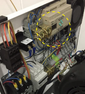
High Pressure Pump PLC
Adjusting the PLC to increase the time for pump to pressurize before timing out: The PLC Screen shown inside yellow dotted area. The time delay is pre-set at the factory for 25 seconds.
• Note: The steps below will basically double the amount of time (25 seconds to 65 seconds) of the factory setting. The setting can be raised up to a maximum of 99 seconds if needed.
• Steps to adjust the delay timer for the high pressure switch signal.
Power up the PLC.
From the main screen:
1. Press OK button, screen will change
2. Use the down arrow to get to Parameter
3. Press OK, screen will change
4. ‘0’ will be changing from darkened to lightened. Press OK
5. ‘0’ will be blinking
6. Press the down arrow until the ‘0’ changes to a ‘b’
7. Press OK, ‘b’ will begin flashing with a darkened square.
8. Press the Down arrow, the curser will drop down to the last ‘0’ on the ’25.00’ number at the bottom right hand side of the display.
9. Press OK, the ‘0’ will begin blinking
10. Press the left arrow 3 times to move the cursor to the ‘2’ of the ’25.00’ number.
11. Press the up arrow to change the ‘2’ to a ‘6’
12. Press OK
13. Press ESC 2 times to return to the operational screen (timer now set for 65 seconds)
All of our humidification systems function as a unified system, fully integrated and automated including a PLC controlled pump, zone humidistat/sensor and fans. The pumps are prewired to the humidistat for testing during production and ship ready to install.
So, the system functions in the following manner: a humidistat/sensor (for each zone) sends a start signal to the pump whenever humidity is required (based on the settings in the humidistat). Once the humidistat/sensor reaches the required humidity level, the start signal is terminated.
When the pump receives the start signal from the humidistat, the PLC sequentially turns on any fans that are part of the system; then the water supply to the pump, then the pump motor. The delays between these functions can be programmed to factory set timing sequences consistent with each project as require. Upon termination of the start signal, the PLC then sequentially stops the operation of the pump motor, then the valves, then the fans (if they are part of the system). The time between this sequential shut down is also programmable and can be set based on the system or project requirements.
The PLC also handles the signal from the high pressure safety switch. It will provide a delay (sufficient time to let the system fully charge). This delay also allows for a loss of pressure for a short period of time (as when a second zone is opened while the system is already running thereby temporarily dropping the output pressure) without immediately terminating the system. IF the pressure is lost beyond the set time (as when the water supply has been terminated OR there is a breech in the high pressure line resulting in a loss of high pressure in the system), the PLC will shut down the system and provide a signal to the red Pressure Fault indicator light included on the pump side panel. The PLC requires a ‘reset’ to allow the system to begin operating again.
The plc also controls a green indicator light for when the pump is operating and a yellow indicator light which illuminates after a programmed period of time – typically 500 hours – providing a notice that it is time to change the oil, check for leaks from the pump seals, check the pulley belts for wear, check the filters for possible replacement, etc…
The PLC is the brains of our pump systems and can be programmed to do whatever is needed in terms of system functionality. Although we do have a standard program, we can and do provide customized programs for clients that have specific operational requirements.
Currently, we also use the PLC to track things like the number of pressure faults, the number of on/off cycles, and the total run time of the pump.