How to Check the Unloader Valve (Pressure Regulator)
Installed in a “Tri-Plex Plunger Type”
General High Pressure Humidification Pump
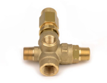
High Pressure General Pump Unloader Valve (Pressure Regulator)
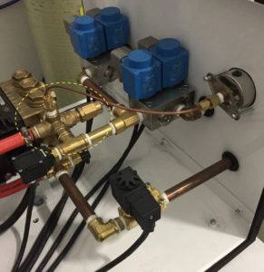
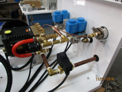
Unloader Valve Shown Installed in High Pressure Pump Station
This is a pressure regulator and bypass valve as a combined function in one valve that is plumbed on the outlet side of the pump and allows the pressure output for the pump to be controlled (typically at 1000 psi) AND it allows any excess water from the output to be re-routed back to the pump inlet or to a holding tank depending on the system design.
The unloader valve has seals and excessive bypass through the unloader valve will cause seals to wear prematurely. Seals should last many years. Excessive bypass occurs because the pump strains on the output side struggling to maintain greater than 50% output for extended periods of time. We always seek to design pump size such that no single zone is significantly under 50% output at any time. The cure for this the inclusion in the pump design of VFD (variable frequency drive).
One sign of a defective regulator/unloader valve are pressure spikes. The pressure may not be constant where a reading can be seen on the pressure gauge – but might be “spiking”. To inspect the unloader, remove the acorn nut that has a hole in the end of it. It is located on the output manifold of the pump. The picture shows what a defective unloader/regulator valve looks like – it will have rust in it or on the spring – and will usually need to be replaced. If no rust, you can spray WD 40 in it and loosen/tighten to ensure it is freed up. The pressure should read 1000 psi while in operation.
Checking/Inspecting the Unloader/Regulator Valve if Malfunctioning:
- Turn the unit off.
- Locate the acorn nut that has a hole in the end of it – it is located on the output manifold of the pump.
- Mark how tight the acorn nut is currently threaded on.
- Un-thread the nut from the valve completely.
- Inspect the thick spring on the inside.
- If it is rusted or corroded, it needs to be replaced.
- If it is still clean (like shiny or polished steel), thread the nut back on however tight it was.
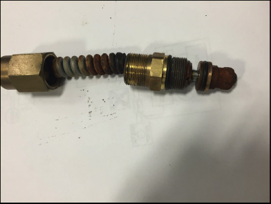
Defective Rusted Unloader/Regulator Valve
Instructions for the Replacement of the Unloader Valve
The process to remove the unloader valve involves a sequential removal and reassembly of all components and fittings from the 3/2 valves to the unloader valve.
- Take several images of the plumbing before starting making special note of how far each fitting is threaded into its corresponding fitting to ensure everything is properly aligned when the reassembly is completed.
- Remove the fittings for the Outlet and Drain ports on the outer side of the housing
- Remove the blue coils from the two 3/2 valves noting which set of coils goes to zone 1 and zone 2.
- Unthread the two 3/2 valve blocks from the fittings that feed the valves
- Unthread the 90-degree elbow/nipple assembly from the brass street T fitting
- Unthread the brass street T fitting/nipple assembly from the brass T
- Remove the silver clip from the high-pressure switch and remove the switch from its brass base fitting
- Unthread the brass T from the unloader valve
- Remove the hose clamp from the bypass hose that is attached to the unloader valve
- Unthread the bypass hose fitting from the unloader valve
- Unthread the compression cap from the fitting that is attached to the top of the unloader valve
- Remove the small ferrule from inside the fitting noting the position it is in and set aside. It will be used when reassembling the fitting.
- Push the copper tubing aside
- Unthread the base of the compression fitting from the unloader.
- Unthread the unloader from the pump. The extension that is threaded into the end of the unloader valve (that the hexed cap is threaded onto) may have to be removed to provide enough clearance to unthread the unloader valve.
- Make sure each fitting has sufficient Teflon tape applied before threading into place. 6 to 8 revolutions of Teflon is recommended for each male thread.
- Thread the new unloader in place
- The extension on the end of the unloader may have to be removed to provide clearance to thread the unloader into the pump.
- Reassemble the plumbing in the reverse order in which it was removed making sure each fitting is threaded approximately the same depth as the original assembly.
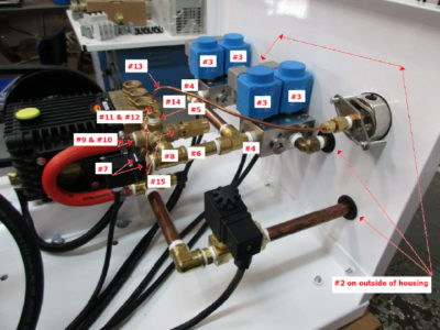
Replacing Unloader Valve with Numbered Steps
Replacing Unloader Valve