Category

Pump Maintenance and Trouble Shooting

Correct Position of the Diaphragm in the Inlet Water Solenoid Valve

By | Pump Maintenance and Trouble Shooting

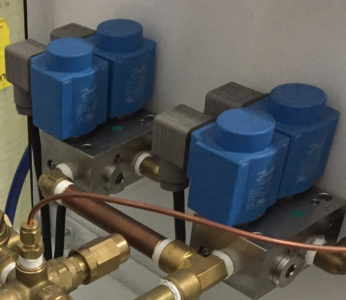
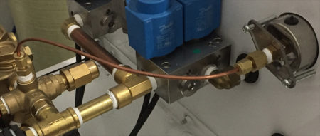
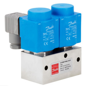
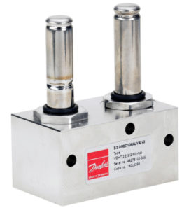
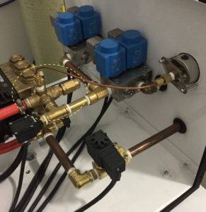
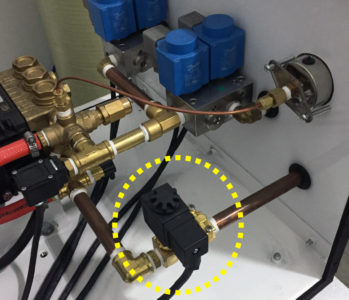
The Inlet Water Solenoid Valve is the first piece of hardware which the treated water supply to the high pressure pump enters.  Its’ function as a valve is to prevent low pressure water from flowing thru the pump while it is OFF or in STANDBY, and to allow water to flow thru to the pump while it is ON.

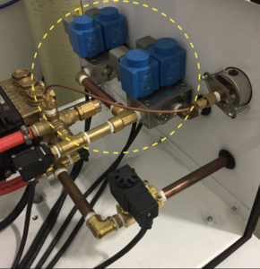
The graphic shows the location of the inlet water solenoid valve circled in yellow.

Supply water inlet solenoid valve (installed) for high pressure humidity control system

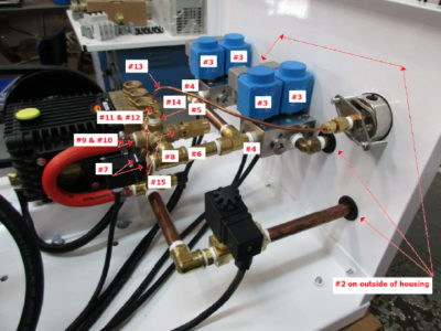
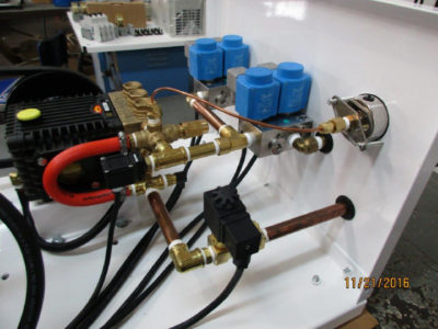
Supply water inlet solenoid valve (installed) in the Inlet Water Line  for a High Pressure Humidity Control System


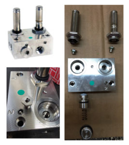
The diaphragm inside the inlet water solenoid valve is the internal viton rubber component that prevents flow when the valve is not energized and allows flow when it is energized.  When the diaphragm is out of position or damaged, it may restrict flow when the valve is energized and it may allow water to flow when the valve is not energized.  Therefore, it is important to make sure when removing and inspecting the diaphragm, to replace it correctly vs incorrectly.  The following graphics are provided showing the top and bottom of the diaphragm and the correct positioning of the diaphragm when installed in the water solenoid valve.


Top view of diaphragm for water inlet solenoid valve for a humidity control high pressure pump

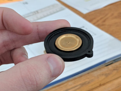
Top view of the diaphragm for the water inlet solenoid valve for a humidity control high pressure pump.


Bottom view of diaphragm for water inlet solenoid valve for a humidity control high pressure pump

Bottom view of the diaphragm for the water inlet solenoid valve for a humidity control high pressure pump.


Top view of diaphragm installed CORRECTLY in a water inlet solenoid valve for a humidity control high pressure pump

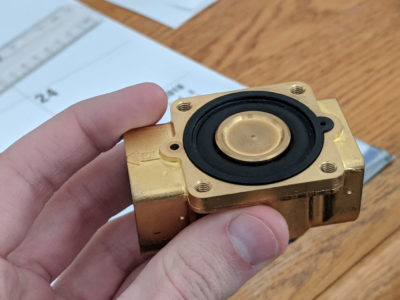
Top view of the diaphragm installed CORRECTLY in a water inlet solenoid valve for a humidity control high pressure pump.


Diaphragm INCORRECTLY installed in a water inlet solenoid valve for a humidity control high pressure pump

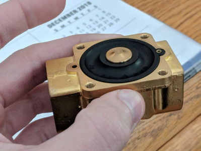
The Diaphragm INCORRECTLY installed in a water inlet solenoid valve for a humidity control high pressure pump

Checking the Coil, the DIN Connector, and the Power to the DIN Connector

By | Pump Maintenance and Trouble Shooting

Inspecting the Danfoss EDV Valve and the Danfoss 3/2 Valves with EDV for signs of malfunction, should first include an inspection to make sure the DIN Connector and Power Cord are functioning correctly.  The following is a description of checking the DIN Connector with an image below showing four DIN Connectors connected to Zone Danfoss 3/2 Valves with EDV (drain) function built in.

Checking the coil, theDIN connector, and the power to theDIN connector is suggested as follows:

Initially, if you place your fingers on the coil and turn the pump on, you should feel the internal piston ‘clicking’ into position which means the coil, theDIN, and the valve are probably working as needed.  You can also sometimes hear the clicking (if it is a relatively quiet pump).

If you cannot determine the valve function using this simple test, check the coil by simply looking at it to make sure there are no protrusions (caused by a short in the coil and a resulting ‘explosion’ that changes the outer profile of the coil body).  You will typically see a bulging side or an actual hole in the coil body.

If the coil looks bad, it will need to be replaced.  To determine the cause (which is not always determinable), remove the coil from the valve stem and inspect the valve stem to see if there is any discoloration or rust or the presence of water that would cause the coil to short.  If there is, the valve stem will need to be replaced.  We have seen some of these stems fail at the point of the weld around the circumference of the stem allowing water to leak out which then causes the coil to fail.

If the coil does not look bad, remove the small Phillips screw from the front face of theDIN connector (the connector is the component that is attached to the three prongs on the coil) and remove theDIN connector from the coil.  Check the prongs for discoloration (usually carbon buildup as a result of a short circuit).  If there is obvious damage, the dDIN will need to be replaced.  This failure can be caused by moisture but more likely caused by the connections in theDIN connector being crossed or two of the wires touching.

If none of this leads to an answer, I would next place theDIN back on the coil leaving enough room to get the prongs from a multi meter between theDIN and the coil so that you can touch each prong to one of the top two prongs check to make sure the coil is actually getting the power from the source.  If there is no power at these prongs, then the power source for the coil is not being energized.

This is a standard DIN connector used with the Humidity Control Pump Station System.  It is used to provide the power supply to the valve coil (the blue component on the Danfoss valve and the black component on the Granzow [solenoid] valve).

DIN Connector and Power Cord to Danfoss 3/2 Valve

DIN Connector (gray) and Power Cord to Danfoss (blue) 3/2 Valves

Humidity Control Pre-Season Startup “Maintenance Checklist” for High Pressure Systems

By | Pump Maintenance and Trouble Shooting

Pre-Season “Maintenance Checklist” for Humidity Control System Startup

Regularly scheduled maintenance is the best preventative maintenance procedure to minimize unexpected breakdowns.  Learn to watch for signs from your pump station operation which may indicate maintenance may be needed.  The most common signs of needed maintenance are: a drop in pressure, fluctuating pressure, vibration, unusual noises, external leaking of water or oil, excessive pump heat, water in crankcase oil, and premature wear of parts.
The typical seasonal period for adding humidity begins around Oct 15 and ends around April 15.  Typically, there are two procedures for “year round” operation of the humidity control system.
  1. End of Season Shut Down: Shutting down (turning off) the total operation of the humidity control system for the off season requires all high pressure lines drained of water, OR;
  2. Leave the system operational all year, and during the off season, run the system for ten minutes once every two weeks to maintain fresh water in the lines – Note: You will need to set the humidistat(s) higher than indoor humidity levels in order to operate the system during the off season.
PRE-SEASON MAINTENANCE CHECKLIST:
  • Maintain a maintenance service log with date and maintenance performed.
  • Make a record of total pump hours as recorded on the pump hour meter at beginning of season.
  • Change the pump 5 micron sediment pre-filter at least once per operating season or clean as needed.
  • Check oil level and change once per year or every 500 hours of pump operation, whichever comes first.
  • Service Pump Packings and Seals every 2-2500 hours.
  • Check pulley belt which should have no more than 1/2” flex.
  • After system startup, check all nozzles for uniform spray pattern.  Some nozzles may need to be cleaned and reinserted. Tip: a simple procedure for cleaning nozzles – the head of the nozzle unscrews and the spring and ball with the valve can be removed. Soak all pieces in warm vinegar and water solution or soak in “Works” toilet bowl cleaner for 60 seconds, rinse and reassemble – you should have a new working nozzle with restored performance.
  • Note: In all cases where system operation may be malfunctioning, the first place to check are the fuses.  

How to Change the Belt on a High Pressure Humidity Control General “Type” Pump

By | Pump Maintenance and Trouble Shooting

Alignment of Motor:

The motor for the high pressure pump is mounted to a 2 piece base plate that allows the adjustment of the motor position (left and right) without having to loosen the 4 motor mounting bolts.  This ‘tension’ bolt is located on the back side of the motor base plate and moves the top section of the motor base plate to adjust tension.

IF the motor and pump pulley are not properly aligned (visually identified by making sure the two pulleys are parallel to each other) , it will usually be a matter of loosening the four motor mounting bolts and slightly shifting the position of the motor until the pulley is ‘squared’ to the pump pulley.  The belt will have to be removed to release any tension and allow the motor to be slightly shifted.  This is rarely an issue but if the motor has shifted, this is how to remedy motor alignment for correct pulley operation with the high pressure pump as pictured.

Guidelines for Changing the Belt:

• The first thing you want to do is mark the existing location of the pump head base plate against the bottom of the housing.   This will help you line it back up easier.   A small black sharpie works well.

• Loosen the four bolts on the pump head base.

• Slide the pump head towards the motor.  This should allow you to get the old belt off.

• Put the new belt on.

• Slide the pump head back to the marks you made.    It is very important that the pump is lined up straight.   If not, it will cause premature wear of the belt.    To help with this, you can take a small piece of pipe or straight edge to ensure it is square on the outside of the pulley.    Your marks will also assist with this.

• The belt should be snug enough once you push the pump head back in place.  Make sure it does not flex more than 1/2″.

Motor and Pulley Alignment of Belt with General Type High Pressure Pump

Motor and Pulley Alignment of Belt with General Type High Pressure Pump